abdulati suleiman

YOUR WINDOW HERE

Saturday, October 9, 2010

Flight Instruments

Flight Instruments

Flight instruments enable an airplane to be operated with maximum performance and enhanced safety, especially when flying long distances. Manufacturers provide the necessary instruments, but to use them effectively, pilots need to understand how they operate. This page covers the operational aspects of the pitot-static system and associated instruments, the vacuum system and associated instruments, and the magnetic compass.

Pitot-static flight instruments

There are two major parts of the pitot-static system: the impact pressure chamber and lines, and the static pressure chamber and lines. They provide the source of ambient air pressure for the operation of the altimeter, vertical speed indicator (vertical velocity indicator), and the airspeed indicator.

Figure 1: Pitot-static system and instruments.

Impact pressure chamber and lines

In this system, the impact air pressure (air striking the airplane because of its forward motion) is taken from a pitot tube, which is mounted in locations that provide minimum disturbance or turbulence caused by the motion of the airplane through the air. The static pressure (pressure of the still air) is usually taken from the static line attached to a vent or vents mounted flush with the side of the fuselage. This compensates for any possible variation in static pressure due to erratic changes in airplane attitude.

The openings of both the pitot tube and the static vent must be checked during the preflight inspection to assure that they are free from obstructions. Blocked or partially blocked openings should be cleaned by a certificated mechanic. Blowing into these openings is not recommended because this could damage the instruments.

As the airplane moves through the air, the impact pressure on the open pitot tube affects the pressure in the pitot chamber. Any change of pressure in the pitot chamber is transmitted through a line connected to the airspeed indicator, which utilizes impact pressure for its operation.

Static pressure chamber and lines

The static chamber is vented through small holes to the free undisturbed air, and as the atmospheric pressure increases or decreases, the pressure in the static chamber changes accordingly. Again, this pressure change is transmitted through lines to the flight instruments which utilize static pressure.

An alternate source for static pressure is provided in some airplanes in the event the static ports become blocked. This source usually is vented to the pressure inside the cockpit. Because of the venturi effect of the flow of air over the cockpit, this alternate static pressure is usually lower than the pressure provided by the normal static air source. When the alternate static source is used, the following differences in the instrument indications usually occur: the altimeter will indicate higher than the actual altitude, the airspeed will indicate greater than the actual airspeed, and the vertical speed will indicate a climb while in level flight.

Consult the Airplane Flight Manual or Pilot’s Operating Handbook (AFM/POH) to determine the amount of error.

If the airplane is not equipped with an alternate static source, breaking the glass seal of the vertical speed indicator allows ambient air pressure to enter the static system. This makes the VSI unusable.

Altimeter

The altimeter measures the height of the airplane above a given pressure level. Since it is the only of the flight instruments that gives altitude information, the altimeter is one of the most vital flight instruments in the airplane. To use the altimeter effectively, its operation and how atmospheric pressure and temperature affect it must be thoroughly understood. A stack of sealed aneroid wafers comprises the main component of the altimeter.

These wafers expand and contract with changes in atmospheric pressure from the static source. The mechanical linkage translates these changes into pointer movements on the indicator.

Figure 2: Altimeter.

Principle of operation

The pressure altimeter is an aneroid barometer that measures the pressure of the atmosphere at the level where the altimeter is located, and presents an altitude indication in feet. The altimeter uses static pressure as its source of operation. Air is denser at sea level than aloft, so as altitude increases, atmospheric pressure decreases. This difference in pressure at various levels causes the altimeter to indicate changes in altitude.

The presentation of altitude varies considerably between different types of altimeters. Some have one pointer while others have two or more. Only the multipointer type will be discussed on this page.

The dial of a typical altimeter is graduated with numerals arranged clockwise from 0 to 9. Movement of the aneroid element is transmitted through gears to the three hands that indicate altitude. The shortest hand indicates altitude in tens of thousands of feet; the intermediate hand in thousands of feet; and the longest hand in hundreds of feet.

This indicated altitude is correct, however, only when the sea level barometric pressure is standard (29.92 inches of mercury), the sea level free air temperature is standard (+15°C or 59°F), and the pressure and temperature decrease at a standard rate with an increase in altitude. Adjustments for nonstandard conditions are accomplished by setting the corrected pressure into a barometric scale located on the face of the altimeter.

Only after the altimeter is set does it indicate the correct altitude.

Effect of nonstandard pressure and temperature

If no means were provided for adjusting altimeters to nonstandard pressure, flight could be hazardous. For example, if flying from a high-pressure area to a low-pressure area without adjusting the altimeter, the actual altitude of the airplane would be LOWER than the indicated altitude. An old saying, “HIGH TO LOW, LOOK OUT BELOW” is a way of remembering which condition is dangerous. When flying from a low-pressure area to a high-pressure area without adjusting the altimeter, the actual altitude of the airplane is HIGHER than the indicated altitude.

Figure 3: Effects of nonstandard temperature on an altimeter.

Figure 3 shows how variations in air temperature also affect the altimeter. On a warm day, a given mass of air expands to a larger volume than on a cold day, raising the pressure levels. For example, the pressure level where the altimeter indicates 5,000 feet is HIGHER on a warm day than under standard conditions. On a cold day, the reverse is true, and the pressure level where the altimeter indicates 5,000 feet is LOWER.

The adjustment to compensate for nonstandard pressure does not compensate for nonstandard temperature.

If terrain or obstacle clearance is a factor in selecting a cruising altitude, particularly at higher altitudes, remember to anticipate that a colder-than-standard temperature places the airplane LOWER than the altimeter indicates. Therefore, it is necessary to use a higher indicated altitude to provide adequate terrain clearance. Modify the memory aid to “HIGH TO LOW OR HOT TO COLD, LOOK OUT BELOW.”

Setting the altimeter

Most altimeters are equipped with a barometric pressure setting window (sometimes referred to as the Kollsman window) providing a means to adjust the altimeter. A knob is located at the bottom of the instrument for this adjustment.

To adjust the altimeter for variation in atmospheric pressure, the pressure scale in the altimeter setting window, calibrated in inches of mercury (in. Hg) and/or millibars (Mb), is adjusted to match the given altimeter setting. Altimeter setting is defined as station pressure reduced to sea level. However, an altimeter setting is accurate only in the vicinity of the reporting station.

Therefore, the altimeter must be adjusted as the flight progresses from one station to the next.

Many pilots confidently expect that the current altimeter setting will compensate for irregularities in atmospheric pressure at all altitudes, but this is not always true. The altimeter setting broadcast by ground stations is the station pressure corrected to mean sea level. It does not account for the irregularities at higher levels, particularly the effect of nonstandard temperature. However, if each pilot in a given area is using the same altimeter setting, each altimeter should be equally affected by temperature and pressure variation errors, making it possible to maintain the desired vertical separation between aircraft.

When flying over high, mountainous terrain, certain atmospheric conditions can cause the altimeter to indicate an altitude of 1,000 feet, or more, HIGHER than the actual altitude. For this reason, a generous margin of altitude should be allowed—not only for possible altimeter error, but also for possible downdrafts that might be associated with high winds.

To illustrate the use of the altimeter setting system, follow a flight from Dallas Love Field, Texas to Abilene Municipal Airport, Texas via Mineral Wells.

Before taking off from Love Field, the pilot receives a current altimeter setting of 29.85 from the control tower or automatic terminal information service (ATIS), and sets this value in the altimeter setting window. The altimeter indication should then be compared with the known airport elevation of 487 feet.

Since most altimeters are not perfectly calibrated, an error may exist.

When over Mineral Wells, assume the pilot receives a current altimeter setting of 29.94 and sets this in the altimeter window. Before entering the traffic pattern at Abilene Municipal Airport, a new altimeter setting of 29.69 is received from the Abilene Control Tower, and set in the altimeter setting window. If the pilot desires to fly the traffic pattern at approximately 800 feet above the terrain, and the field elevation of Abilene is 1,791 feet, an indicated altitude of 2,600 feet should be maintained (1,791 feet + 800 feet = 2,591 feet rounded to 2,600 feet).

The importance of properly setting the altimeter cannot be overemphasized. Assume that the pilot did not adjust the altimeter at Abilene to the current setting, and continued using the Mineral Wells setting of 29.94.

When entering the Abilene traffic pattern at an indicated altitude of 2,600 feet, the airplane would be approximately 250 feet below the proper traffic pattern altitude. Upon landing, the altimeter would indicate approximately 250 feet higher than the field elevation.

Altimeter setting 29.94

Current altimeter setting 29.69

Difference .25

(Since 1 inch of pressure is equal to approximately 1,000 feet of altitude,

.25 * 1,000 feet = 250 feet.)

When determining whether to add or subtract the amount of altimeter error, remember that, when the actual pressure is lower than what is set in the altimeter window, the actual altitude of the airplane will be lower than what is indicated on the altimeter.

Altimeter operation

There are two means by which the altimeter pointers can be moved. The first is a change in air pressure, while the other is an adjustment to the barometric scale. When the airplane climbs or descends, changing pressure within the altimeter case expands or contracts the aneroid barometer. This movement is transmitted through mechanical linkage to rotate the pointers. A decrease in pressure causes the altimeter to indicate an increase in altitude, and an increase in pressure causes the altimeter to indicate a decrease in altitude.

Accordingly, if the airplane is flown from a pressure level of 28.75 in. Hg. to a pressure level of 29.75 in. Hg., the altimeter would show a decrease of approximately 1,000 feet in altitude.

The other method of moving the pointers does not rely on changing air pressure, but the mechanical construction of the altimeter. Do not be confused by the fact that as the barometric pressure scale is moved, the indicator needles move in the same direction, which is opposite to the reaction the pointers have when air pressure changes. To illustrate this point, suppose the pilot lands at an airport with an elevation of 1,000 feet and the altimeter is correctly set to the current sea level pressure of 30.00 in. Hg. While the airplane is parked on the ramp, the pressure decreases to 29.50. The altimeter senses this as a climb and now indicates 1,500 feet.

When returning to the airplane, if the setting in the altimeter window is decreased to the current sea level pressure of 29.50, the indication will be reduced back down to 1,000 feet.

Knowing the airplane’s altitude is vitally important to a pilot. The pilot must be sure that the airplane is flying high enough to clear the highest terrain or obstruction along the intended route. It is especially important to have accurate altitude information when visibility is restricted. To clear obstructions, the pilot must constantly be aware of the altitude of the airplane and the elevation of the surrounding terrain. To reduce the possibility of a midair collision, it is essential to maintain altitude in accordance with air traffic rules.

Types of altitude

Altitude is vertical distance above some point or level used as a reference. There are as many kinds of altitude as there are reference levels from which altitude is measured, and each may be used for specific reasons.

Pilots are mainly concerned with five types of altitudes:

Indicated Altitude—That altitude read directly from the altimeter (uncorrected) when it is set to the current altimeter setting.

True Altitude—The vertical distance of the airplane above sea level—the actual altitude. It is often expressed as feet above mean sea level (MSL). Airport, terrain, and obstacle elevations on aeronautical charts are true altitudes.

Absolute Altitude—The vertical distance of an airplane above the terrain, or above ground level (AGL).

Pressure Altitude—The altitude indicated when the altimeter setting window (barometric scale) is adjusted to 29.92. This is the altitude above the standard datum plane, which is a theoretical plane where air pressure (corrected to 15°C) equals 29.92 in. Hg. Pressure altitude is used to compute density altitude, true altitude, true airspeed, and other performance data.

Density Altitude—This altitude is pressure altitude corrected for variations from standard temperature.

When conditions are standard, pressure altitude and density altitude are the same. If the temperature is above standard, the density altitude is higher than pressure altitude. If the temperature is below standard, the density altitude is lower than pressure altitude. This is an important altitude because it is directly related to the airplane’s performance.

As an example, consider an airport with a field elevation of 5,048 feet MSL where the standard temperature is 5°C. Under these conditions, pressure altitude and density altitude are the same—5,048 feet.

If the temperature changes to 30°C, the density altitude increases to 7,855 feet. This means an airplane would perform on takeoff as though the field elevation were 7,855 feet at standard temperature. Conversely, a temperature of -25°C would result in a density altitude of 1,232 feet. An airplane would have much better performance under these conditions.

Instrument Check—To determine the condition of an altimeter, set the barometric scale to the altimeter setting transmitted by the local automated flight service station (AFSS) or any other reliable source. The altimeter pointers should indicate the surveyed elevation of the airport. If the indication is off more than 75 feet from the surveyed elevation, the instrument should be referred to a certificated instrument repair station for recalibration.

Vertical speed indicator

The vertical speed indicator (VSI), which is sometimes called a vertical velocity indicator (VVI), indicates whether the airplane is climbing, descending, or in level flight. The rate of climb or descent is indicated in feet per minute. If properly calibrated, the VSI indicates zero in level flight.

Figure 4: Vertical speed indicator.

Principle of operation

Although the vertical speed indicator operates solely from static pressure, it is a differential pressure instrument. It contains a diaphragm with connecting linkage and gearing to the indicator pointer inside an airtight case. The inside of the diaphragm is connected directly to the static line of the pitot-static system.

The area outside the diaphragm, which is inside the instrument case, is also connected to the static line, but through a restricted orifice (calibrated leak).

Both the diaphragm and the case receive air from the static line at existing atmospheric pressure. When the airplane is on the ground or in level flight, the pressures inside the diaphragm and the instrument case remain the same and the pointer is at the zero indication. When the airplane climbs or descends, the pressure inside the diaphragm changes immediately, but due to the metering action of the restricted passage, the case pressure remains higher or lower for a short time, causing the diaphragm to contract or expand. This causes a pressure differential that is indicated on the instrument needle as a climb or descent. When the pressure differential stabilizes at a definite ratio, the needle indicates the rate of altitude change.

The vertical speed indicator is capable of displaying two different types of information:

  • Trend information shows an immediate indication of an increase or decrease in the airplane’s rate of climb or descent.
  • Rate information shows a stabilized rate of change in altitude.

For example, if maintaining a steady 500-foot per minute (f.p.m.) climb, and the nose is lowered slightly, the VSI immediately senses this change and indicates a decrease in the rate of climb. This first indication is called the trend. After a short time, the VSI needle stabilizes on the new rate of climb, which in this example, is something less than 500 f.p.m. The time from the initial change in the rate of climb, until the VSI displays an accurate indication of the new rate, is called the lag. Rough control technique and turbulence can extend the lag period and cause erratic and unstable rate indications. Some airplanes are equipped with an instantaneous vertical speed indicator (IVSI), which incorporates accelerometers to compensate for the lag in the typical VSI.

Figure 5: An instantaneous vertical speed indicator incorporates accelerometers to help the instrument immediately indicate changes in vertical speed.

Instrument Check—To verify proper operation, make sure the VSI is indicating near zero prior to takeoff.

After takeoff, it should indicate a positive rate of climb.

Airspeed indicator

The airspeed indicator is a sensitive, differential pressure gauge which measures and shows promptly the difference between pitot or impact pressure, and static pressure, the undisturbed atmospheric pressure at level flight. These two pressures will be equal when the airplane is parked on the ground in calm air. When the airplane moves through the air, the pressure on the pitot line becomes greater than the pressure in the static lines. This difference in pressure is registered by the airspeed pointer on the face of the instrument, which is calibrated in miles per hour, knots, or both.

Figure 6: Airspeed indicator.

Pilots should understand the following speeds:

Indicated Airspeed (IAS)—The direct instrument reading obtained from the airspeed indicator, uncorrected for variations in atmospheric density, installation error, or instrument error. Manufacturers use this airspeed as the basis for determining airplane performance. Takeoff, landing, and stall speeds listed in the AFM or POH are indicated airspeeds and do not normally vary with altitude or temperature.

Calibrated Airspeed (CAS)—Indicated airspeed corrected for installation error and instrument error.

Although manufacturers attempt to keep airspeed errors to a minimum, it is not possible to eliminate all errors throughout the airspeed operating range. At certain airspeeds and with certain flap settings, the installation and instrument errors may total several knots. This error is generally greatest at low airspeeds.

In the cruising and higher airspeed ranges, indicated airspeed and calibrated airspeed are approximately the same. Refer to the airspeed calibration chart to correct for possible airspeed errors.

True Airspeed (TAS)—Calibrated airspeed corrected for altitude and nonstandard temperature. Because air density decreases with an increase in altitude, an airplane has to be flown faster at higher altitudes to cause the same pressure difference between pitot impact pressure and static pressure. Therefore, for a given calibrated airspeed, true airspeed increases as altitude increases; or for a given true airspeed, calibrated airspeed decreases as altitude increases.

A pilot can find true airspeed by two methods. The most accurate method is to use a flight computer. With this method, the calibrated airspeed is corrected for temperature and pressure variation by using the airspeed correction scale on the computer. Extremely accurate electronic flight computers are also available.

Just enter the CAS, pressure altitude, and temperature and the computer calculates the true airspeed.

A second method, which is a “rule of thumb,” will provide the approximate true airspeed. Simply add 2 percent to the calibrated airspeed for each 1,000 feet of altitude.

Groundspeed (GS)—The actual speed of the airplane over the ground. It is true airspeed adjusted for wind.

Groundspeed decreases with a headwind, and increases with a tailwind.

Airspeed indicator markings

Airplanes weighing 12,500 pounds or less, manufactured after 1945, and certificated by the FAA, are required to have airspeed indicators marked in accordance with a standard color-coded marking system. This system of color-coded markings enables a pilot to determine at a glance certain airspeed limitations that are important to the safe operation of the airplane. For example, if during the execution of a maneuver, it is noted that the airspeed needle is in the yellow arc and rapidly approaching the red line, the immediate reaction should be to reduce airspeed.

Figure 7: In addition to delineating various speed ranges, the boundaries of the color-coded arcs also identify airspeed limitations.

As shown in figure 7, airspeed indicators on single engine small airplanes include the following standard color-coded markings:

  • White arc—This arc is commonly referred to as the flap operating range since its lower limit represents the full flap stall speed and its upper limit provides the maximum flap speed.

Approaches and landings are usually flown at speeds within the white arc.

  • Lower limit of white arc (VS0)—The stalling speed or the minimum steady flight speed in the landing configuration. In small airplanes, this is the power-off stall speed at the maximum landing weight in the landing configuration (gear and flaps down).
  • Upper limit of the white arc (VFE)—The maximum speed with the flaps extended.
  • Green arc—This is the normal operating range of the airplane. Most flying occurs within this range.
  • Lower limit of green arc (VS1)—The stalling speed or the minimum steady flight speed obtained in a specified configuration. For most airplanes, this is the power-off stall speed at the maximum takeoff weight in the clean configuration (gear up, if retractable, and flaps up).
  • Upper limit of green arc (VNO)—The maximum structural cruising speed. Do not exceed this speed except in smooth air.
  • Yellow arc—Caution range. Fly within this range only in smooth air, and then, only with caution.
  • Red line (VNE)—Never-exceed speed. Operating above this speed is prohibited since it may result in damage or structural failure.

Other airspeed limitations

Some important airspeed limitations are not marked on the face of the airspeed indicator, but are found on placards and in the AFM or POH. These airspeeds include:

  • Design maneuvering speed (VA)—This is the “rough air” speed and the maximum speed for abrupt maneuvers. If during flight, rough air or severe turbulence is encountered, reduce the airspeed to maneuvering speed or less to minimize stress on the airplane structure. It is important to consider weight when referencing this speed. For example, VA may be 100 knots when an airplane is heavily loaded, but only 90 knots when the load is light.
  • Landing gear operating speed (VLO)—The maximum speed for extending or retracting the landing gear if using an airplane equipped with retractable landing gear.
  • Landing gear extended speed (VLE)—The maximum speed at which an airplane can be safely flown with the landing gear extended.
  • Best angle-of-climb speed (VX)—The airspeed at which an airplane gains the greatest amount of altitude in a given distance. It is used during a short-field takeoff to clear an obstacle.
  • Best rate-of-climb speed (VY)—This airspeed provides the most altitude gain in a given period of time.
  • Minimum control speed (VMC)—This is the minimum flight speed at which a light, twin-engine airplane can be satisfactorily controlled when an engine suddenly becomes inoperative and the remaining engine is at takeoff power.
  • Best rate of climb with one engine inoperative (VYSE)—This airspeed provides the most altitude gain in a given period of time in a light, twinengine airplane following an engine failure.

Instrument Check—Prior to takeoff, the airspeed indicator should read zero. However, if there is a strong wind blowing directly into the pitot tube, the airspeed indicator may read higher than zero. When beginning the takeoff, make sure the airspeed is increasing at an appropriate rate.

Blockage of the pitot-static system

Errors almost always indicate blockage of the pitot tube, the static port(s), or both. Blockage may be caused by moisture (including ice), dirt, or even insects. During preflight, make sure the pitot tube cover is removed. Then, check the pitot and static port openings. A blocked pitot tube affects the accuracy of only the airspeed indicator.

However, a blockage of the static system not only affects the airspeed indicator, but can also cause errors in the altimeter and vertical speed indicator.

Blocked pitot system

The pitot system can become blocked completely or only partially if the pitot tube drain hole remains open.

If the pitot tube becomes blocked and its associated drain hole remains clear, ram air no longer is able to enter the pitot system. Air already in the system will vent through the drain hole, and the remaining pressure will drop to ambient (outside) air pressure. Under these circumstances, the airspeed indicator reading decreases to zero, because the airspeed indicator senses no difference between ram and static air pressure. The airspeed indicator acts as if the airplane were stationary on the ramp. The apparent loss of airspeed is not usually instantaneous. Instead, the airspeed will drop toward zero.

Figure 8: A blocked pitot tube, but clear drain hole.

If the pitot tube, drain hole, and static system all become blocked in flight, changes in airspeed will not be indicated, due to the trapped pressures. However, if the static system remains clear, the airspeed indicator acts as an altimeter. An apparent increase in the ram air pressure relative to static pressure occurs as altitude increases above the level where the pitot tube and drain hole became blocked. This pressure differential causes the airspeed indicator to show an increase in speed. A decrease in indicated airspeed occurs as the airplane descends below the altitude at which the pitot system became blocked.

Figure 9: Blocked pitot system with clear static system.

The pitot tube may become blocked during flight through visible moisture. Some airplanes may be equipped with pitot heat for flight in visible moisture.

Consult the AFM or POH for specific procedures regarding the use of pitot heat.

Blocked static system

If the static system becomes blocked but the pitot tube remains clear, the airspeed indicator continues to operate; however, it is inaccurate. Airspeed indications are slower than the actual speed when the airplane is operated above the altitude where the static ports became blocked, because the trapped static pressure is higher than normal for that altitude. When operating at a lower altitude, a faster than actual airspeed is displayed due to the relatively low static pressure trapped in the system.

A blockage of the static system also affects the altimeter and VSI. Trapped static pressure causes the altimeter to freeze at the altitude where the blockage occurred. In the case of the VSI, a blocked static system produces a continuous zero indication.

Figure 10: Blocked static system.

Gyroscopic flight instruments

Several flight instruments utilize the properties of a gyroscope for their operation. The most common flight instruments containing gyroscopes are the turn coordinator, heading indicator, and the attitude indicator. To understand how these flight instruments operate requires knowledge of the instrument power systems, gyroscopic principles, and the operating principles of each instrument.

Gyroscopic principles

Any spinning object exhibits gyroscopic properties. A wheel or rotor designed and mounted to utilize these properties is called a gyroscope. Two important design characteristics of an instrument gyro are great weight for its size, or high density, and rotation at high speed with low friction bearings.

There are two general types of mountings; the type used depends upon which property of the gyro is utilized. A freely or universally mounted gyroscope is free to rotate in any direction about its center of gravity. Such a wheel is said to have three planes of freedom. The wheel or rotor is free to rotate in any plane in relation to the base and is so balanced that with the gyro wheel at rest, it will remain in the position in which it is placed. Restricted or semirigidly mounted gyroscopes are those mounted so that one of the planes of freedom is held fixed in relation to the base.

There are two fundamental properties of gyroscopic action—rigidity in space and precession.

Rigidity in space

Rigidity in space refers to the principle that a gyroscope remains in a fixed position in the plane in which it is spinning. By mounting this wheel, or gyroscope, on a set of gimbal rings, the gyro is able to rotate freely in any direction. Thus, if the gimbal rings are tilted, twisted, or otherwise moved, the gyro remains in the plane in which it was originally spinning.

Figure 11: Regardless of the position of its base, a gyro tends to remain rigid in space, with its axis of rotation pointed in a constant direction.

Precession

Precession is the tilting or turning of a gyro in response to a deflective force. The reaction to this force does not occur at the point where it was applied; rather, it occurs at a point that is 90° later in the direction of rotation.

This principle allows the gyro to determine a rate of turn by sensing the amount of pressure created by a change in direction. The rate at which the gyro precesses is inversely proportional to the speed of the rotor and proportional to the deflective force.

Precession can also create some minor errors in some flight instruments.

Figure 12: Precession of a gyroscope resulting from an applied deflective force.

Sources of power

In some airplanes, all the gyros are vacuum, pressure, or electrically operated; in others, vacuum or pressure systems provide the power for the heading and attitude indicators, while the electrical system provides the power for the turn coordinator. Most airplanes have at least two sources of power to ensure at least one source of bank information if one power source fails.

The vacuum or pressure system spins the gyro by drawing a stream of air against the rotor vanes to spin the rotor at high speed, much like the operation of a waterwheel or turbine. The amount of vacuum or pressure required for instrument operation varies, but is usually between 4.5 and 5.5 in. Hg.

One source of vacuum for the gyros is a vane-type engine-driven pump that is mounted on the accessory case of the engine. Pump capacity varies in different airplanes, depending on the number of gyros.

A typical vacuum system consists of an engine-driven vacuum pump, relief valve, air filter, gauge, and tubing necessary to complete the connections. The gauge is mounted in the airplane’s instrument panel and indicates the amount of pressure in the system (vacuum is measured in inches of mercury less than ambient pressure).

Figure 13: Typical Vacuum System.

As shown in figure 13, air is drawn into the vacuum system by the engine-driven vacuum pump. It first goes through a filter, which prevents foreign matter from entering the vacuum or pressure system. The air then moves through the attitude and heading indicators, where it causes the gyros to spin. A relief valve prevents the vacuum pressure, or suction, from exceeding prescribed limits. After that, the air is expelled overboard or used in other systems, such as for inflating pneumatic deicing boots.

It is important to monitor vacuum pressure during flight, because the attitude and heading indicators may not provide reliable information when suction pressure is low. The vacuum, or suction, gauge generally is marked to indicate the normal range. Some airplanes are equipped with a warning light that illuminates when the vacuum pressure drops below the acceptable level.

Turn indicators

Airplanes use two types of turn indicators—the turn-and-slip indicator and the turn coordinator. Because of the way the gyro is mounted, the turn-and-slip indicator only shows the rate of turn in degrees per second.

Because the gyro on the turn coordinator is set at an angle, or canted, it can initially also show roll rate.

Once the roll stabilizes, it indicates rate of turn.

Both flight instruments indicate turn direction and quality (coordination), and also serve as a backup source of bank information in the event an attitude indicator fails. Coordination is achieved by referring to the inclinometer, which consists of a liquid-filled curved tube with a ball inside.

Figure 14: Turn indicators rely on controlled precession for their operation.

Turn-and-slip indicator

The gyro in the turn-and-slip indicator rotates in the vertical plane, corresponding to the airplane’s longitudinal axis. A single gimbal limits the planes in which the gyro can tilt, and a spring tries to return it to center. Because of precession, a yawing force causes the gyro to tilt left or right as viewed from the pilot seat.

The turn-and-slip indicator uses a pointer, called the turn needle, to show the direction and rate of turn.

Turn coordinator

The gimbal in the turn coordinator is canted; therefore, its gyro can sense both rate of roll and rate of turn.

Since turn coordinators are more prevalent in training airplanes, this discussion concentrates on that instrument.

When rolling into or out of a turn, the miniature airplane banks in the direction the airplane is rolled. A rapid roll rate causes the miniature airplane to bank more steeply than a slow roll rate.

The turn coordinator can be used to establish and maintain a standard-rate-turn by aligning the wing of the miniature airplane with the turn index. The turn coordinator indicates only the rate and direction of turn; it does not display a specific angle of bank.

Inclinometer

The inclinometer is used to depict airplane yaw, which is the side-to-side movement of the airplane’s nose.

During coordinated, straight-and-level flight, the force of gravity causes the ball to rest in the lowest part of the tube, centered between the reference lines. Coordinated flight is maintained by keeping the ball centered. If the ball is not centered, it can be centered by using the rudder.

To do this, apply rudder pressure on the side where the ball is deflected. Use the simple rule, “step on the ball,” to remember which rudder pedal to press.

Figure 15: If inadequate right rudder is applied in a right turn, a slip results. Too much right rudder causes the airplane to skid through the turn. Centering the ball results in a coordinated turn.

If aileron and rudder are coordinated during a turn, the ball remains centered in the tube. If aerodynamic forces are unbalanced, the ball moves away from the center of the tube. As shown in figure 15, in a slip, the rate of turn is too slow for the angle of bank, and the ball moves to the inside of the turn. In a skid, the rate of turn is too great for the angle of bank, and the ball moves to the outside of the turn. To correct for these conditions, and improve the quality of the turn, remember to “step on the ball.” Varying the angle of bank can also help restore coordinated flight from a slip or skid.

To correct for a slip, decrease bank and/or increase the rate of turn. To correct for a skid, increase the bank and/or decrease the rate of turn.

Instrument Check—During the preflight, check to see that the inclinometer is full of fluid and has no air bubbles. The ball should also be resting at its lowest point. When taxiing, the turn coordinator should indicate a turn in the correct direction.

The attitude indicator

The attitude indicator, with its miniature airplane and horizon bar, displays a picture of the attitude of the airplane.

The relationship of the miniature airplane to the horizon bar is the same as the relationship of the real airplane to the actual horizon. The instrument gives an instantaneous indication of even the smallest changes in attitude.

The gyro in the attitude indicator is mounted on a horizontal plane and depends upon rigidity in space for its operation. The horizon bar represents the true horizon.

This bar is fixed to the gyro and remains in a horizontal plane as the airplane is pitched or banked about its lateral or longitudinal axis, indicating the attitude of the airplane relative to the true horizon.

Figure 16: Attitude indicator. Adjustment Gears Adjustment

An adjustment knob is provided with which the pilot may move the miniature airplane up or down to align the miniature airplane with the horizon bar to suit the pilot’s line of vision. Normally, the miniature airplane is adjusted so that the wings overlap the horizon bar when the airplane is in straight-and-level cruising flight.

The pitch and bank limits depend upon the make and model of the instrument. Limits in the banking plane are usually from 100° to 110°, and the pitch limits are usually from 60° to 70°. If either limit is exceeded, the instrument will tumble or spill and will give incorrect indications until restabilized. A number of modern attitude indicators will not tumble.

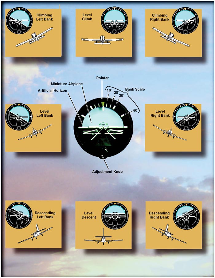
Figure 17: Attitude representation by the attitude indicator corresponds to that of the airplane to the real horizon.

Every pilot should be able to interpret the banking scale illustrated in figure 17. Most banking scale indicators on the top of the instrument move in the same direction from that in which the airplane is actually banked.

Some other models move in the opposite direction from that in which the airplane is actually banked. This may confuse the pilot if the indicator is used to determine the direction of bank. This scale should be used only to control the degree of desired bank. The relationship of the miniature airplane to the horizon bar should be used for an indication of the direction of bank.

The attitude indicator is reliable and the most realistic flight instrument on the instrument panel. Its indications are very close approximations of the actual attitude of the airplane.

Heading indicator

The heading indicator (or directional gyro) is fundamentally a mechanical instrument designed to facilitate the use of the magnetic compass. Errors in the magnetic compass are numerous, making straight flight and precision turns to headings difficult to accomplish, particularly in turbulent air. A heading indicator, however, is not affected by the forces that make the magnetic compass difficult to interpret.

Figure 18: A heading indicator displays headings based on a 360° azimuth, with the final zero omitted. For example, a 6 represents 060°, while a 21 indicates 210°. The adjustment knob is used to align the heading indicator with the magnetic compass.

The operation of the heading indicator depends upon the principle of rigidity in space. The rotor turns in a vertical plane, and fixed to the rotor is a compass card.

Since the rotor remains rigid in space, the points on the card hold the same position in space relative to the vertical plane. As the instrument case and the airplane revolve around the vertical axis, the card provides clear and accurate heading information.

Because of precession, caused by friction, the heading indicator will creep or drift from a heading to which it is set. Among other factors, the amount of drift depends largely upon the condition of the instrument. If the bearings are worn, dirty, or improperly lubricated, the drift may be excessive. Another error in the heading indicator is caused by the fact that the gyro is oriented in space, and the earth rotates in space at a rate of 15° in 1 hour. Thus, discounting precession caused by friction, the heading indicator may indicate as much as 15° error per every hour of operation.

Some heading indicators receive a magnetic north reference from a magnetic slaving transmitter, and generally need no adjustment. Heading indicators that do not have this automatic north-seeking capability are called “free” gyros, and require periodic adjustment. It is important to check the indications frequently (approximately every 15 minutes) and reset the heading indicator to align it with the magnetic compass when required.

Adjust the heading indicator to the magnetic compass heading when the airplane is straight and level at a constant speed to avoid compass errors.

The bank and pitch limits of the heading indicator vary with the particular design and make of instrument. On some heading indicators found in light airplanes, the limits are approximately 55° of pitch and 55° of bank.

When either of these attitude limits is exceeded, the instrument “tumbles” or “spills” and no longer gives the correct indication until reset. After spilling, it may be reset with the caging knob. Many of the modern flight instruments used are designed in such a manner that they will not tumble.

Instrument Check—As the gyro spools up, make sure there are no abnormal sounds. While taxiing, the instrument should indicate turns in the correct direction, and precession should not be abnormal. At idle power settings, the gyroscopic flight instruments using the vacuum system might not be up to operating speeds and precession might occur more rapidly than during flight.

Magnetic compass

Since the magnetic compass works on the principle of magnetism, it is well for the pilot to have at least a basic understanding of magnetism. A simple bar magnet has two centers of magnetism which are called poles. Lines of magnetic force flow out from each pole in all directions, eventually bending around and returning to the other pole. The area through which these lines of force flow is called the field of the magnet. For the purpose of this discussion, the poles are designated “north” and “south.” If two bar magnets are placed near each other, the north pole of one will attract the south pole of the other. There is evidence that there is a magnetic field surrounding the Earth, and this theory is applied in the design of the magnetic compass. It acts very much as though there were a huge bar magnet running along the axis of the Earth which ends several hundred miles below the surface.

Figure 19: Earth’s magnetic field.

The geographic north and south poles form the axis for the Earth’s rotation. These positions are also referred to as true north and south. Another axis is formed by the magnetic north and south poles. Lines of magnetic force flow out from each pole in all directions, and eventually return to the opposite pole. A compass aligns itself with the magnetic axis formed by the north/south magnetic field of the Earth.

The lines of force have a vertical component (or pull) which is zero at the Equator, but builds to 100 percent of the total force at the magnetic poles. If magnetic needles, such as in the airplane’s magnetic compass, are held along these lines of force, the vertical component causes one end of the needle to dip or deflect downward. The amount of dip increases as the needles are moved closer and closer to the poles. It is this deflection, or dip, that causes some of the larger compass errors.

The magnetic compass, which is usually the only direction-seeking instrument in the airplane, is simple in construction. It contains two steel magnetized needles fastened to a float, around which is mounted a compass card. The needles are parallel, with their north-seeking ends pointing in the same direction. The compass card has letters for cardinal headings, and each 30° interval is represented by a number, the last zero of which is omitted. For example, 30° appears as a 3 and 300° appears as a 30. Between these numbers, the card is graduated for each 5°. The magnetic compass is required equipment in all airplanes. It is used to set the gyroscopic heading indicator, correct for precession, and as a backup in the event the heading indicator(s) fails.

Figure 20: Magnetic compass.

Compass errors

Variation

Although the magnetic field of the Earth lies roughly north and south, the Earth’s magnetic poles do not coincide with its geographic poles, which are used in the construction of aeronautical charts. Consequently, at most places on the Earth’s surface, the direction-sensitive steel needles that seek the Earth’s magnetic field will not point to true north, but to magnetic north.

Furthermore, local magnetic fields from mineral deposits and other conditions may distort the Earth’s magnetic field, and cause additional error in the position of the compass’ north-seeking magnetized needles with reference to true north.

The angular difference between magnetic north, the reference for the magnetic compass, and true north is variation. Lines that connect points of equal variation are called isogonic lines. The line connecting points where the magnetic variation is zero is an agonic line.

To convert from true courses or headings to magnetic, subtract easterly variation and add westerly variation.

Reverse the process to convert from magnetic to true.

Figure 21: Variation at point A in the western United States is 17°. Since the magnetic north pole is located to the east of the true north pole in relation to this point, the variation is easterly. When the magnetic pole falls to the west of the true north pole, variation is westerly.

Compass deviation

Besides the magnetic fields generated by the Earth, other magnetic fields are produced by metal and electrical accessories within the airplane. These magnetic fields distort the Earth’s magnetic force, and cause the compass to swing away from the correct heading.

This error is called deviation. Manufacturers install compensating magnets within the compass housing to reduce the effects of deviation. The magnets are usually adjusted while the engine is running and all electrical equipment is operating. However, it is not possible to completely eliminate deviation error; therefore, a compass correction card is mounted near the compass. This card corrects for deviation that occurs from one heading to the next as the lines of force interact at different angles.

Figure 22: Compass correction card.

Magnetic dip

Magnetic dip is the result of the vertical component of the Earth’s magnetic field. This dip is virtually non-existent at the magnetic equator, since the lines of force are parallel to the Earth’s surface and the vertical component is minimal. When a compass is moved toward the poles, the vertical component increases, and magnetic dip becomes more apparent at higher latitudes. Magnetic dip is responsible for compass errors during acceleration, deceleration, and turns.

Using the magnetic compass

Acceleration/deceleration errors

Acceleration and deceleration errors are fluctuations in the compass during changes in speed. In the Northern Hemisphere, the compass swings towards the north during acceleration, and towards the south during deceleration. When the speed stabilizes, the compass returns to an accurate indication. This error is most pronounced when flying on a heading of east or west, and decreases gradually when flying closer to a north or south heading. The error does not occur when flying directly north or south. The memory aid, ANDS (Accelerate North, Decelerate South) may help in recalling this error. In the Southern Hemisphere, this error occurs in the opposite direction.

Turning errors

Turning errors are most apparent when turning to or from a heading of north or south. This error increases as the poles are neared and magnetic dip becomes more apparent. There is no turning error when flying near the magnetic equator.

In the Northern Hemisphere, when making a turn from a northerly heading, the compass gives an initial indication of a turn in the opposite direction. It then begins to show the turn in the proper direction, but lags behind the actual heading. The amount of lag decreases as the turn continues, then disappears as the airplane reaches a heading of east or west. When turning from a heading of east or west to a heading of north, there is no error as the turn begins. However, as the heading approaches north, the compass increasingly lags behind the airplane’s actual heading. When making a turn from a southerly heading, the compass gives an indication of a turn in the correct direction, but leads the actual heading. This error also disappears as the airplane approaches an east or west heading. Turning from east or west to a heading of south causes the compass to move correctly at the start of a turn, but then it increasingly leads the actual heading as the airplane nears a southerly direction.

The amount of lead or lag is approximately equal to the latitude of the airplane. For example, if turning from a heading of south to a heading of west while flying at 40° north latitude, the compass rapidly turns to a heading of 220° (180° + 40°). At the midpoint of the turn, the lead decreases to approximately half (20°), and upon reaching a heading of west, it is zero.

The magnetic compass, which is the only direction-seeking instrument in the airplane, should be read only when the airplane is flying straight and level at a constant speed.

This will help reduce errors to a minimum.

If the pilot thoroughly understands the errors and characteristics of the magnetic compass, this instrument can become the most reliable means of determining headings.

Instrument Check—Prior to flight, make sure that the compass is full of fluid. Then during turns, the compass should swing freely and indicate known headings.

Vertical card compass

A newer design, the vertical card compass significantly reduces the inherent error of the older compass designs.

It consists of an azimuth on a rotating vertical card, and resembles a heading indicator with a fixed miniature airplane to accurately present the heading of the airplane.

The presentation is easy to read, and the pilot can see the complete 360° dial in relation to the airplane heading. This design uses eddy current damping to minimize lead and lag during turns.

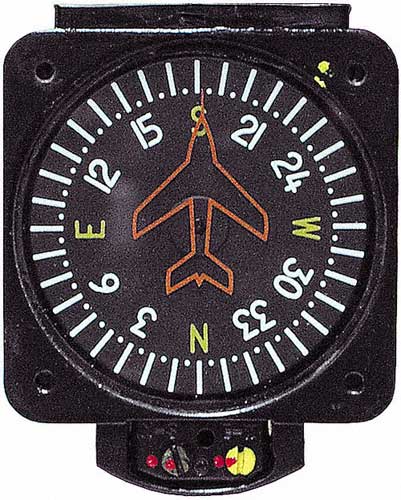
Figure 23: Vertical card compass.

Outside air temperature gauge

The outside air temperature gauge (OAT) is a simple and effective device mounted so that the sensing element is exposed to the outside air. The sensing element consists of a bimetallic-type thermometer in which two dissimilar materials are welded together in a single strip and twisted into a helix.

One end is anchored into protective tube and the other end is affixed to the pointer, which reads against the calibration on a circular face. OAT gauges are calibrated in degrees Celsius, Fahrenheit, or both. An accurate air temperature will provide the pilot with useful information about temperature lapse rate with altitude change.

Figure 24: Outside air temperature gauge.

Aeronautics

Aeronautics: influence of airplane design characteristics on stability and handling of aircraft.

Airplane design characteristics

Every pilot who has flown numerous types of airplanes has noted that each airplane handles somewhat differently—that is, each resists or responds to control pressures in its own way. A training type airplane is quick to respond to control applications, while a transport airplane usually feels heavy on the controls and responds to control pressures more slowly. These features can be designed into an airplane to facilitate the particular purpose the airplane is to fulfill by considering certain stability and maneuvering requirements. In the following discussion, it is intended to summarize the more important aspects of an airplane’s stability; its maneuvering and controllability qualities; how they are analyzed; and their relationship to various flight conditions. In brief, the basic differences between stability, maneuverability, and controllability are as follows:

Stability—The inherent quality of an airplane to correct for conditions that may disturb its equilibrium, and to return or to continue on the original flightpath. It is primarily an airplane design characteristic.

Maneuverability—The quality of an airplane that permits it to be maneuvered easily and to withstand the stresses imposed by maneuvers. It is governed by the airplane’s weight, inertia, size and location of flight controls, structural strength, and powerplant. It too is an airplane design characteristic.

Controllability—The capability of an airplane to respond to the pilot’s control, especially with regard to flightpath and attitude. It is the quality of the airplane’s response to the pilot’s control application when maneuvering the airplane, regardless of its stability characteristics.

Basic concepts of stability

The flightpaths and attitudes in which an airplane can fly are limited only by the aerodynamic characteristics of the airplane, its propulsive system, and its structural strength. These limitations indicate the maximum performance and maneuverability of the airplane. If the airplane is to provide maximum utility, it must be safely controllable to the full extent of these limits without exceeding the pilot’s strength or requiring exceptional flying ability. If an airplane is to fly straight and steady along any arbitrary flightpath, the forces acting on it must be in static equilibrium. The reaction of any body when its equilibrium is disturbed is referred to as stability.

There are two types of stability; static and dynamic.

Static will be discussed first, and in this discussion the following definitions will apply:

Equilibrium—All opposing forces acting on the airplane are balanced; (i.e., steady, unaccelerated flight conditions).

Static Stability—The initial tendency that the airplane displays after its equilibrium is disturbed.

Positive Static Stability—The initial tendency of the airplane to return to the original state of equilibrium after being disturbed.

Negative Static Stability—The initial tendency of the airplane to continue away from the original state of equilibrium after being disturbed.

Neutral Static Stability—The initial tendency of the airplane to remain in a new condition after its equilibrium has been disturbed.

Figure 1: Types of stability.

Static stability

Stability of an airplane in flight is slightly more complex than just explained, because the airplane is free to move in any direction and must be controllable in pitch, roll, and direction. When designing the airplane, engineers must compromise between stability, maneuverability, and controllability; and the problem is compounded because of the airplane’s three-axis freedom. Too much stability is detrimental to maneuverability, and similarly, not enough stability is detrimental to controllability. In the design of airplanes, compromise between the two is the keyword.

Dynamic stability

Static stability has been defined as the initial tendency that the airplane displays after being disturbed from its trimmed condition. Occasionally, the initial tendency is different or opposite from the overall tendency, so distinction must be made between the two. Dynamic stability is the overall tendency that the airplane displays after its equilibrium is disturbed. The curves of figure 2 represent the variation of controlled functions versus time. It is seen that the unit of time is very significant. If the time unit for one cycle or oscillation is above 10 seconds’ duration, it is called a “long-period” oscillation (phugoid) and is easily controlled. In a longitudinal phugoid oscillation, the angle of attack remains constant when the airspeed increases and decreases. To a certain degree, a convergent phugoid is desirable but is not required. The phugoid can be determined only on a statically stable airplane, and this has a great effect on the trimming qualities of the airplane. If the time unit for one cycle or oscillation is less than one or two seconds, it is called a “short-period” oscillation and is normally very difficult, if not impossible, for the pilot to control. This is the type of oscillation that the pilot can easily “get in phase with” and reinforce.

Figure 2: Damped versus undamped stability.

A neutral or divergent, short-period oscillation is dangerous because structural failure usually results if the oscillation is not damped immediately.

Short-period oscillations affect airplane and control surfaces alike and reveal themselves as “porpoising” in the airplane, or as in “buzz” or “flutter” in the control surfaces. Basically, the short-period oscillation is a change in angle of attack with no change in airspeed. A short-period oscillation of a control surface is usually of such high frequency that the airplane does not have time to react. Logically, the Code of Federal Regulations require that short-period oscillations be heavily damped (i.e., die out immediately).

Flight tests during the airworthiness certification of airplanes are conducted for this condition by inducing the oscillation in the controls for pitch, roll, or yaw at the most critical speed (i.e., at VNE, the never-exceed speed). The test pilot strikes the control wheel or rudder pedal a sharp blow and observes the results.

Longitudinal stability (pitching)

In designing an airplane, a great deal of effort is spent in developing the desired degree of stability around all three axes. But longitudinal stability about the lateral axis is considered to be the most affected by certain variables in various flight conditions.

Longitudinal stability is the quality that makes an airplane stable about its lateral axis. It involves the pitching motion as the airplane’s nose moves up and down in flight. Alongitudinally unstable airplane has a tendency to dive or climb progressively into a very steep dive or climb, or even a stall. Thus, an airplane with longitudinal instability becomes difficult and sometimes dangerous to fly.

Static longitudinal stability or instability in an airplane, is dependent upon three factors:

1. Location of the wing with respect to the center of gravity;

2. Location of the horizontal tail surfaces with respect to the center of gravity; and

3. The area or size of the tail surfaces.

In analyzing stability, it should be recalled that a body that is free to rotate will always turn about its center of gravity.

To obtain static longitudinal stability, the relation of the wing and tail moments must be such that, if the moments are initially balanced and the airplane is suddenly nosed up, the wing moments and tail moments will change so that the sum of their forces will provide an unbalanced but restoring moment which, in turn, will bring the nose down again.

Similarly, if the airplane is nosed down, the resulting change in moments will bring the nose back up.

The center of lift, sometimes called the center of pressure, in most unsymmetrical airfoils has a tendency to change its fore and aft position with a change in the angle of attack. The center of pressure tends to move forward with an increase in angle of attack and to move aft with a decrease in angle of attack. This means that when the angle of attack of an airfoil is increased, the center of pressure (lift) by moving forward, tends to lift the leading edge of the wing still more. This tendency gives the wing an inherent quality of instability.

Figure 3 shows an airplane in straight-and-level flight. The line CG-CL-T represents the airplane’s longitudinal axis from the center of gravity (CG) to a point T on the horizontal stabilizer. The center of lift (or center of pressure) is represented by the point CL.

Figure 3: Longitudinal stability.

Most airplanes are designed so that the wing’s center of lift (CL) is to the rear of the center of gravity. This makes the airplane “nose heavy” and requires that there be a slight downward force on the horizontal stabilizer in order to balance the airplane and keep the nose from continually pitching downward.

Compensation for this nose heaviness is provided by setting the horizontal stabilizer at a slight negative angle of attack. The downward force thus produced, holds the tail down, counterbalancing the “heavy” nose. It is as if the line CG-CL-T was a lever with an upward force at CL and two downward forces balancing each other, one a strong force at the CG point and the other, a much lesser force, at point T (downward air pressure on the stabilizer). Applying simple physics principles, it can be seen that if an iron bar were suspended at point CL with a heavy weight hanging on it at the CG, it would take some downward pressure at point T to keep the “lever” in balance.

Even though the horizontal stabilizer may be level when the airplane is in level flight, there is a downwash of air from the wings. This downwash strikes the top of the stabilizer and produces a downward pressure, which at a certain speed will be just enough to balance the “lever.” The faster the airplane is flying, the greater this downwash and the greater the downward force on the horizontal stabilizer (except “T” tails).

Figure 4: Effect of speed on downwash.

In airplanes with fixed position horizontal stabilizers, the airplane manufacturer sets the stabilizer at an angle that will provide the best stability (or balance) during flight at the design cruising speed and power setting.

Figure 5: Reduced power allows pitch down.

If the airplane’s speed decreases, the speed of the airflow over the wing is decreased. As a result of this decreased flow of air over the wing, the downwash is reduced, causing a lesser downward force on the horizontal stabilizer. In turn, the characteristic nose heaviness is accentuated, causing the airplane’s nose to pitch down more. This places the airplane in a nose-low attitude, lessening the wing’s angle of attack and drag and allowing the airspeed to increase. As the airplane continues in the nose-low attitude and its speed increases, the downward force on the horizontal stabilizer is once again increased.

Consequently, the tail is again pushed downward and the nose rises into a climbing attitude. As this climb continues, the airspeed again decreases, causing the downward force on the tail to decrease until the nose lowers once more. However, because the airplane is dynamically stable, the nose does not lower as far this time as it did before. The airplane will acquire enough speed in this more gradual dive to start it into another climb, but the climb is not so steep as the preceding one.

After several of these diminishing oscillations, in which the nose alternately rises and lowers, the airplane will finally settle down to a speed at which the downward force on the tail exactly counteracts the tendency of the airplane to dive. When this condition is attained, the airplane will once again be in balanced flight and will continue in stabilized flight as long as this attitude and airspeed are not changed.

A similar effect will be noted upon closing the throttle. The downwash of the wings is reduced and the force at T in figure 3 is not enough to hold the horizontal stabilizer down. It is as if the force at T on the lever were allowing the force of gravity to pull the nose down. This, of course, is a desirable characteristic because the airplane is inherently trying to regain airspeed and reestablish the proper balance.

Power or thrust can also have a destabilizing effect in that an increase of power may tend to make the nose rise. The airplane designer can offset this by establishing a “high thrustline” wherein the line of thrust passes above the center of gravity.

Figure 6: Thrust line affects longitudinal stability.

Figure 7: Power changes affect longitudinal stability.

In this case, as power or thrust is increased a moment is produced to counteract the down load on the tail. On the other hand, a very “low thrust line” would tend to add to the nose-up effect of the horizontal tail surface.

It can be concluded, then, that with the center of gravity forward of the center of lift, and with an aerodynamic tail-down force, the result is that the airplane always tries to return to a safe flying attitude.

A simple demonstration of longitudinal stability may be made as follows: Trim the airplane for “hands off” control in level flight. Then momentarily give the controls a slight push to nose the airplane down. If, within a brief period, the nose rises to the original position and then stops, the airplane is statically stable. Ordinarily, the nose will pass the original position (that of level flight) and a series of slow pitching oscillations will follow. If the oscillations gradually cease, the airplane has positive stability; if they continue unevenly, the airplane has neutral stability; if they increase, the airplane is unstable.

Lateral stability (rolling)

Stability about the airplane’s longitudinal axis, which extends from nose to tail, is called lateral stability. This helps to stabilize the lateral or rolling effect when one wing gets lower than the wing on the opposite side of the airplane. There are four main design factors that make an airplane stable laterally: dihedral, keel effect, sweepback, and weight distribution.

The most common procedure for producing lateral stability is to build the wings with a dihedral angle varying from one to three degrees. In other words, the wings on either side of the airplane join the fuselage to form a slight V or angle called “dihedral,” and this is measured by the angle made by each wing above a line parallel to the lateral axis.

The basis of rolling stability is, of course, the lateral balance of forces produced by the airplane’s wings. Any imbalance in lift results in a tendency for the airplane to roll about its longitudinal axis.

Stated another way, dihedral involves a balance of lift created by the wings’ angle of attack on each side of the airplane’s longitudinal axis.

If a momentary gust of wind forces one wing of the airplane to rise and the other to lower, the airplane will bank. When the airplane is banked without turning, it tends to sideslip or slide downward toward the lowered wing.

Figure 8: Dihedral for lateral stability.

Since the wings have dihedral, the air strikes the low wing at much greater angle of attack than the high wing. This increases the lift on the low wing and decreases lift on the high wing, and tends to restore the airplane to its original lateral attitude (wings level)—that is, the angle of attack and lift on the two wings are again equal.

The effect of dihedral, then, is to produce a rolling moment tending to return the airplane to a laterally balanced flight condition when a sideslip occurs.

The restoring force may move the low wing up too far, so that the opposite wing now goes down. If so, the process will be repeated, decreasing with each lateral oscillation until a balance for wings-level flight is finally reached.

Conversely, excessive dihedral has an adverse effect on lateral maneuvering qualities. The airplane may be so stable laterally that it resists any intentional rolling motion. For this reason, airplanes that require fast roll or banking characteristics usually have less dihedral than those designed for less maneuverability.

The contribution of sweepback to dihedral effect is important because of the nature of the contribution.

In a sideslip, the wing into the wind is operating with an effective decrease in sweepback, while the wing out of the wind is operating with an effective increase in sweepback. The swept wing is responsive only to the wind component that is perpendicular to the wing’s leading edge. Consequently, if the wing is operating at a positive lift coefficient, the wing into the wind has an increase in lift, and the wing out of the wind has a decrease in lift. In this manner, the swept back wing would contribute a positive dihedral effect and the swept forward wing would contribute a negative dihedral effect.

During flight, the side area of the airplane’s fuselage and vertical fin react to the airflow in much the same manner as the keel of a ship. That is, it exerts a steadying influence on the airplane laterally about the longitudinal axis.

Such laterally stable airplanes are constructed so that the greater portion of the keel area is above and behind the center of gravity.

Figure 9: Keel area for lateral stability.

Thus, when the airplane slips to one side, the combination of the airplane’s weight and the pressure of the airflow against the upper portion of the keel area (both acting about the CG) tends to roll the airplane back to wings-level flight.

Vertical stability (yawing)

Stability about the airplane’s vertical axis (the sideways moment) is called yawing or directional stability.

Yawing or directional stability is the more easily achieved stability in airplane design. The area of the vertical fin and the sides of the fuselage aft of the center of gravity are the prime contributors which make the airplane act like the well known weathervane or arrow, pointing its nose into the relative wind.

In examining a weathervane, it can be seen that if exactly the same amount of surface were exposed to the wind in front of the pivot point as behind it, the forces fore and aft would be in balance and little or no directional movement would result.

Consequently, it is necessary to have a greater surface aft of the pivot point that forward of it.

Similarly in an airplane, the designer must ensure positive directional stability by making the side surface greater aft than ahead of the center of gravity.

Figure 10: Fuselage and fin for vertical stability.

To provide more positive stability aside from that provided by the fuselage, a vertical fin is added. The fin acts similar to the feather on an arrow in maintaining straight flight.

Like the weathervane and the arrow, the farther aft this fin is placed and the larger its size, the greater the airplane’s directional stability.

If an airplane is flying in a straight line, and a sideward gust of air gives the airplane a slight rotation about its vertical axis (i.e., the right), the motion is retarded and stopped by the fin because while the airplane is rotating to the right, the air is striking the left side of the fin at an angle. This causes pressure on the left side of the fin, which resists the turning motion and slows down the airplane’s yaw. In doing so, it acts somewhat like the weathervane by turning the airplane into the relative wind. The initial change in direction of the airplane’s flightpath is generally slightly behind its change of heading. Therefore, after a slight yawing of the airplane to the right, there is a brief moment when the airplane is still moving along its original path, but its longitudinal axis is pointed slightly to the right.

The airplane is then momentarily skidding sideways, and during that moment (since it is assumed that although the yawing motion has stopped, the excess pressure on the left side of the fin still persists) there is necessarily a tendency for the airplane to be turned partially back to the left. That is, there is a momentary restoring tendency caused by the fin.

This restoring tendency is relatively slow in developing and ceases when the airplane stops skidding. When it ceases, the airplane will be flying in a direction slightly different from the original direction. In other words, it will not of its own accord return to the original heading; the pilot must reestablish the initial heading.

A minor improvement of directional stability may be obtained through sweepback. Sweepback is incorporated in the design of the wing primarily to delay the onset of compressibility during high-speed flight.

In lighter and slower airplanes, sweepback aids in locating the center of pressure in the correct relationship with the center of gravity. A longitudinally stable airplane is built with the center of pressure aft of the center of gravity.

Because of structural reasons, airplane designers sometimes cannot attach the wings to the fuselage at the exact desired point. If they had to mount the wings too far forward, and at right angles to the fuselage, the center of pressure would not be far enough to the rear to result in the desired amount of longitudinal stability. By building sweepback into the wings, however, the designers can move the center of pressure toward the rear. The amount of sweepback and the position of the wings then place the center of pressure in the correct location.

The contribution of the wing to static directional stability is usually small. The swept wing provides a stable contribution depending on the amount of sweepback, but the contribution is relatively small when compared with other components.

Free directional oscillations (Dutch roll)

Dutch Roll is a coupled lateral/directional oscillation that is usually dynamically stable but is objectionable in an airplane because of the oscillatory nature. The damping of the oscillatory mode may be weak or strong depending on the properties of the particular airplane.

Unfortunately all air is not smooth. There are bumps and depressions created by gusty updrafts and downdrafts, and by gusts from ahead, behind, or the side of the airplane.

The response of the airplane to a disturbance from equilibrium is a combined rolling/yawing oscillation in which the rolling motion is phased to precede the yawing motion. The yawing motion is not too significant, but the roll is much more noticeable.

When the airplane rolls back toward level flight in response to dihedral effect, it rolls back too far and sideslips the other way. Thus, the airplane overshoots each time because of the strong dihedral effect. When the dihedral effect is large in comparison with static directional stability, the Dutch Roll motion has weak damping and is objectionable. When the static directional stability is strong in comparison with the dihedral effect, the Dutch Roll motion has such heavy damping that it is not objectionable. However, these qualities tend toward spiral instability.

The choice is then the least of two evils—Dutch Roll is objectionable and spiral instability is tolerable if the rate of divergence is low. Since the more important handling qualities are a result of high static directional stability and minimum necessary dihedral effect, most airplanes demonstrate a mild spiral tendency. This tendency would be indicated to the pilot by the fact that the airplane cannot be flown “hands off” indefinitely.

In most modern airplanes, except high-speed swept wing designs, these free directional oscillations usually die out automatically in a very few cycles unless the air continues to be gusty or turbulent. Those airplanes with continuing Dutch Roll tendencies usually are equipped with gyro stabilized yaw dampers. An airplane that has Dutch Roll tendencies is disconcerting, to say the least. Therefore, the manufacturer tries to reach a medium between too much and too little directional stability. Because it is more desirable for the airplane to have “spiral instability” than Dutch Roll tendencies, most airplanes are designed with that characteristic.

Spiral instability

Spiral instability exists when the static directional stability of the airplane is very strong as compared to the effect of its dihedral in maintaining lateral equilibrium. When the lateral equilibrium of the airplane is disturbed by a gust of air and a sideslip is introduced, the strong directional stability tends to yaw the nose into the resultant relative wind while the comparatively weak dihedral lags in restoring the lateral balance. Due to this yaw, the wing on the outside of the turning moment travels forward faster than the inside wing and as a consequence, its lift becomes greater. This produces an overbanking tendency which, if not corrected by the pilot, will result in the bank angle becoming steeper and steeper. At the same time, the strong directional stability that yaws the airplane into the relative wind is actually forcing the nose to a lower pitch attitude. Then, the start of a slow downward spiral which has begun, if not counteracted by the pilot, will gradually increase into a steep spiral dive.

Usually the rate of divergence in the spiral motion is so gradual that the pilot can control the tendency without any difficulty.

All airplanes are affected to some degree by this characteristic although they may be inherently stable in all other normal parameters. This tendency would be indicated to the pilot by the fact that the airplane cannot be flown “hands off” indefinitely.

Much study and effort has gone into development of control devices (wing leveler) to eliminate or at least correct this instability. Advanced stages of this spiral condition demand that the pilot be very careful in application of recovery controls, or excessive loads on the structure may be imposed.

Of the in-flight structural failures that have occurred in general aviation airplanes, improper recovery from this condition has probably been the underlying cause of more fatalities than any other single factor. The reason is that the airspeed in the spiral condition builds up rapidly, and the application of back elevator force to reduce this speed and to pull the nose up only “tightens the turn,” increasing the load factor. The results of the prolonged uncontrolled spiral are always the same; either in-flight structural failure, crashing into the ground, or both. The most common causes on record for getting into this situation are: loss of horizon reference, inability of the pilot to control the airplane by reference to instruments, or a combination of both.

Aerodynamics in flight

Aerodynamics in flight: flight principles applied to airplanes.

Forces acting on the airplane

The following defines these forces in relation to straight-and-level, unaccelerated flight.

Thrust is the forward force produced by the powerplant/propeller. It opposes or overcomes the force of drag. As a general rule, it is said to act parallel to the longitudinal axis. However, this is not always the case as will be explained later.

Drag is a rearward, retarding force, and is caused by disruption of airflow by the wing, fuselage, and other protruding objects. Drag opposes thrust, and acts rearward parallel to the relative wind.

Weight is the combined load of the airplane itself, the crew, the fuel, and the cargo or baggage. Weight pulls the airplane downward because of the force of gravity. It opposes lift, and acts vertically downward through the airplane’s center of gravity.

Lift opposes the downward force of weight, is produced by the dynamic effect of the air acting on the wing, and acts perpendicular to the flightpath through the wing’s center of lift.

Figure 1: Relationship of forces acting on an airplane.

In steady flight, the sum of these opposing forces is equal to zero. There can be no unbalanced forces in steady, straight flight (Newton’s Third Law). This is true whether flying level or when climbing or descending. This is not the same thing as saying that the four forces are all equal. It simply means that the opposing forces are equal to, and thereby cancel the effects of, each other. Often the relationship between the four forces has been erroneously explained or illustrated in such a way that this point is obscured. Consider Figure 1 above, for example. In the upper illustration the force vectors of thrust, drag, lift, and weight appear to be equal in value. The usual explanation states (without stipulating that thrust and drag do not equal weight and lift) that thrust equals drag and lift equals weight as shown in the lower illustration. This basically true statement must be understood or it can be misleading. It should be understood that in straight, level, unaccelerated flight, it is true that the opposing lift/weight forces are equal, but they are also greater than the opposing forces of thrust/drag that are equal only to each other; not to lift/weight. To be correct about it, it must be said that in steady flight:

• The sum of all upward forces (not just lift) equals the sum of all downward forces (not just weight).

• The sum of all forward forces (not just thrust) equals the sum of all backward forces (not just drag).

This refinement of the old “thrust equals drag; lift equals weight” formula takes into account the fact that in climbs a portion of thrust, since it is directed upward, acts as if it were lift; and a portion of weight, since it is directed backward, acts as if it were drag. In glides, a portion of the weight vector is directed forward, and therefore acts as thrust. In other words, any time the flightpath of the airplane is not horizontal, lift, weight, thrust, and drag vectors must each be broken down into two components.

Figure 2: Force vectors during a stabilized climb.

Discussions of the preceding concepts are frequently omitted in aeronautical texts/handbooks/manuals. The reason is not that they are of no consequence, but because by omitting such discussions, the main ideas with respect to the aerodynamic forces acting upon an airplane in flight can be presented in their most essential elements without being involved in the technicalities of the aerodynamicist. In point of fact, considering only level flight, and normal climbs and glides in a steady state, it is still true that wing lift is the really important upward force, and weight is the really important downward force.

Frequently, much of the difficulty encountered in explaining the forces that act upon an airplane is largely a matter of language and its meaning. For example, pilots have long believed that an airplane climbs because of excess lift. This is not true if one is thinking in terms of wing lift alone. It is true, however, if by lift it is meant the sum total of all “upward forces.” But when referring to the “lift of thrust” or the “thrust of weight,” the definitions previously established for these forces are no longer valid and complicate matters. It is this impreciseness in language that affords the excuse to engage in arguments, largely academic, over refinements to basic principles.

Though the forces acting on an airplane have already been defined, a discussion in more detail to establish how the pilot uses them to produce controlled flight is appropriate.

Thrust

Before the airplane begins to move, thrust must be exerted. It continues to move and gain speed until thrust and drag are equal. In order to maintain a constant airspeed, thrust and drag must remain equal, just as lift and weight must be equal to maintain a constant altitude. If in level flight, the engine power is reduced, the thrust is lessened, and the airplane slows down. As long as the thrust is less than the drag, the airplane continues to decelerate until its airspeed is insufficient to support it in the air.

Likewise, if the engine power is increased, thrust becomes greater than drag and the airspeed increases. As long as the thrust continues to be greater than the drag, the airplane continues to accelerate.

When drag equals thrust, the airplane flies at a constant airspeed.

Straight-and-level flight may be sustained at speeds from very slow to very fast. The pilot must coordinate angle of attack and thrust in all speed regimes if the airplane is to be held in level flight. Roughly, these regimes can be grouped in three categories: low-speed flight, cruising flight, and high-speed flight.

When the airspeed is low, the angle of attack must be relatively high to increase lift if the balance between lift and weight is to be maintained.

Figure 3: Angle of attack at various speeds.

If thrust decreases and airspeed decreases, lift becomes less than weight and the airplane will start to descend. To maintain level flight, the pilot can increase the angle of attack an amount which will generate a lift force again equal to the weight of the airplane and while the airplane will be flying more slowly, it will still maintain level flight if the pilot has properly coordinated thrust and angle of attack.

Straight-and-level flight in the slow speed regime provides some interesting conditions relative to the equilibrium of forces, because with the airplane in a nose-high attitude, there is a vertical component of thrust that helps support the airplane. For one thing, wing loading tends to be less than would be expected. Most pilots are aware that an airplane will stall, other conditions being equal, at a slower speed with the power on than with the power off. (Induced airflow over the wings from the propeller also contributes to this.) However, if analysis is restricted to the four forces as they are usually defined, one can say that in straight-and-level slow speed flight the thrust is equal to drag, and lift is equal to weight.

During straight-and level-flight when thrust is increased and the airspeed increases, the angle of attack must be decreased. That is, if changes have been coordinated, the airplane will still remain in level flight but at a higher speed when the proper relationship between thrust and angle of attack is established.

If the angle of attack were not coordinated (decreased) with this increase of thrust, the airplane would climb. But decreasing the angle of attack modifies the lift, keeping it equal to the weight, and if properly done, the airplane still remains in level flight. Level flight at even slightly negative angles of attack is possible at very high speed. It is evident then, that level flight can be performed with any angle of attack between stalling angle and the relatively small negative angles found at high speed.

Drag

Drag in flight is of two basic types: parasite drag and induced drag. The first is called parasite because it in no way functions to aid flight, while the second is induced or created as a result of the wing developing lift.

Parasite drag is composed of two basic elements: form drag, resulting from the disruption of the streamline flow; and the resistance of skin friction.

Of the two components of parasite drag, form drag is the easier to reduce when designing an airplane. In general, a more streamlined object produces the best form to reduce parasite drag.

Skin friction is the type of parasite drag that is most difficult to reduce. No surface is perfectly smooth. Even machined surfaces, when inspected through magnification, have a ragged, uneven appearance. This rough surface will deflect the streamlines of air on the surface, causing resistance to smooth airflow. Skin friction can be minimized by employing a glossy, flat finish to surfaces, and by eliminating protruding rivet heads, roughness, and other irregularities.

Another element must be added to the consideration of parasite drag when designing an airplane. This drag combines the effects of form drag and skin friction and is called interference drag. If two objects are placed adjacent to one another, the resulting turbulence produced may be 50 to 200 percent greater than the parts tested separately.

The three elements, form drag, skin friction, and interference drag, are all computed to determine parasite drag on an airplane.

Shape of an object is a big factor in parasite drag. However, indicated airspeed is an equally important factor when speaking of parasite drag. The profile drag of a streamlined object held in a fixed position relative to the airflow increases approximately as the square of the velocity; thus, doubling the airspeed increases the drag four times, and tripling the airspeed increases the drag nine times. This relationship, however, holds good only at comparatively low subsonic speeds. At some higher airspeeds, the rate at which profile drag has been increased with speed suddenly begins to increase more rapidly.

The second basic type of drag is induced drag. It is an established physical fact that no system, which does work in the mechanical sense, can be 100 percent efficient. This means that whatever the nature of the system, the required work is obtained at the expense of certain additional work that is dissipated or lost in the system. The more efficient the system, the smaller this loss.

In level flight the aerodynamic properties of the wing produce a required lift, but this can be obtained only at the expense of a certain penalty. The name given to this penalty is induced drag. Induced drag is inherent whenever a wing is producing lift and, in fact, this type of drag is inseparable from the production of lift. Consequently, it is always present if lift is produced.

The wing produces the lift force by making use of the energy of the free airstream. Whenever the wing is producing lift, the pressure on the lower surface of the wing is greater than that on the upper surface. As a result, the air tends to flow from the high pressure area below the wingtip upward to the low pressure area above the wing. In the vicinity of the wingtips, there is a tendency for these pressures to equalize, resulting in a lateral flow outward from the underside to the upper surface of the wing. This lateral flow imparts a rotational velocity to the air at the wingtips and trails behind the wing. Therefore, flow about the wingtips will be in the form of two vortices trailing behind as the wings move on.

When the airplane is viewed from the tail, these vortices will circulate counterclockwise about the right wingtip and clockwise about the left wingtip.

Figure 4: Wingtip vortices.

Bearing in mind the direction of rotation of these vortices, it can be seen that they induce an upward flow of air beyond the wingtip, and a downwash flow behind the wing’s trailing edge. This induced downwash has nothing in common with the downwash that is necessary to produce lift. It is, in fact, the source of induced drag. The greater the size and strength of the vortices and consequent downwash component on the net airflow over the wing, the greater the induced drag effect becomes. This downwash over the top of the wing at the tip has the same effect as bending the lift vector rearward; therefore, the lift is slightly aft of perpendicular to the relative wind, creating a rearward lift component. This is induced drag.

It should be remembered that in order to create a greater negative pressure on the top of the wing, the wing can be inclined to a higher angle of attack; also, that if the angle of attack of an asymmetrical wing were zero, there would be no pressure differential and consequently no downwash component; therefore, no induced drag. In any case, as angle of attack increases, induced drag increases proportionally.

To state this another way—the lower the airspeed the greater the angle of attack required to produce lift equal to the airplane’s weight and consequently, the greater will be the induced drag. The amount of induced drag varies inversely as the square of the airspeed.

From the foregoing discussion, it can be noted that parasite drag increases as the square of the airspeed, and induced drag varies inversely as the square of the airspeed. It can be seen that as airspeed decreases to near the stalling speed, the total drag becomes greater, due mainly to the sharp rise in induced drag. Similarly, as the airspeed reaches the terminal velocity of the airplane, the total drag again increases rapidly, due to the sharp increase of parasite drag. As seen in figure 5, at some given airspeed, total drag is at its maximum amount. This is very important in figuring the maximum endurance and range of airplanes; for when drag is at a minimum, power required to overcome drag is also at a minimum.

Figure 5: Drag versus speed.

To understand the effect of lift and drag on an airplane in flight, both must be combined and the lift/drag ratio considered. With the lift and drag data available for various airspeeds of the airplane in steady, unaccelerated flight, the proportions of CL (Coefficient of Lift) and CD (Coefficient of Drag) can be calculated for each specific angle of attack.

The resulting plot for lift/drag ratio with angle of attack shows that L/D increases to some maximum, then decreases at the higher lift coefficients and angles of attack, as shown in figure 6. Note that the maximum lift/drag ratio, (L/D max) occurs at one specific angle of attack and lift coefficient. If the airplane is operated in steady flight at L/D max, the total drag is at a minimum. Any angle of attack lower or higher than that for L/D max reduces the lift/drag ratio and consequently increases the total drag for a given airplane’s lift.

Figure 6: Lift coefficients at various angles of attack.

The location of the center of gravity (CG) is determined by the general design of each particular airplane. The designers determine how far the center of pressure (CP) will travel. They then fix the center of gravity forward of the center of pressure for the corresponding flight speed in order to provide an adequate restoring moment to retain flight equilibrium.

The configuration of an airplane has a great effect on the lift/drag ratio. The high performance sailplane may have extremely high lift/drag ratios. The supersonic fighter may have seemingly low lift/drag ratios in subsonic flight, but the airplane configurations required for supersonic flight (and high L/Ds at high Mach numbers) cause this situation.

Weight

Gravity is the pulling force that tends to draw all bodies to the center of the earth. The center of gravity (CG) may be considered as a point at which all the weight of the airplane is concentrated. If the airplane were supported at its exact center of gravity, it would balance in any attitude. It will be noted that center of gravity is of major importance in an airplane, for its position has a great bearing upon stability.

The location of the center of gravity is determined by the general design of each particular airplane. The designers determine how far the center of pressure (CP) will travel. They then fix the center of gravity forward of the center of pressure for the corresponding flight speed in order to provide an adequate restoring moment to retain flight equilibrium.

Weight has a definite relationship with lift, and thrust with drag. This relationship is simple, but important in understanding the aerodynamics of flying. Lift is the upward force on the wing acting perpendicular to the relative wind. Lift is required to counteract the airplane’s weight (which is caused by the force of gravity acting on the mass of the airplane). This weight (gravity) force acts downward through the airplane’s center of gravity. In stabilized level flight, when the lift force is equal to the weight force, the airplane is in a state of equilibrium and neither gains nor loses altitude.

If lift becomes less than weight, the airplane loses altitude. When the lift is greater than weight, the airplane gains altitude.

Lift

The pilot can control the lift. Any time the control wheel is more fore or aft, the angle of attack is changed. As angle of attack increases, lift increases (all other factors being equal). When the airplane reaches the maximum angle of attack, lift begins to diminish rapidly. This is the stalling angle of attack, or burble point.

Before proceeding further with lift and how it can be controlled, velocity must be interjected. The shape of the wing cannot be effective unless it continually keeps “attacking” new air. If an airplane is to keep flying, it must keep moving. Lift is proportional to the square of the airplane’s velocity. For example, an airplane traveling at 200 knots has four times the lift as the same airplane traveling at 100 knots, if the angle of attack and other factors remain constant.

Actually, the airplane could not continue to travel in level flight at a constant altitude and maintain the same angle of attack if the velocity is increased. The lift would increase and the airplane would climb as a result of the increased lift force. Therefore, to maintain the lift and weight forces in balance, and to keep the airplane “straight and level” (not accelerating upward) in a state of equilibrium, as velocity is increased, lift must be decreased. This is normally accomplished by reducing the angle of attack; i.e., lowering the nose. Conversely, as the airplane is slowed, the decreasing velocity requires increasing the angle of attack to maintain lift sufficient to maintain flight. There is, of course, a limit to how far the angle of attack can be increased, if a stall is to be avoided.

Therefore, it may be concluded that for every angle of attack there is a corresponding indicated airspeed required to maintain altitude in steady, unaccelerated flight—all other factors being constant. (Bear in mind this is only true if maintaining “level flight.”)

Since an airfoil will always stall at the same angle of attack, if increasing weight, lift must also be increased, and the only method for doing so is by increased velocity if the angle of attack is held constant just short of the “critical” or stalling angle of attack.

Lift and drag also vary directly with the density of the air. Density is affected by several factors: pressure, temperature, and humidity. Remember, at an altitude of 18,000 feet, the density of the air has one-half the density of air at sea level. Therefore, in order to maintain its lift at a higher altitude, an airplane must fly at a greater true airspeed for any given angle of attack.

Furthermore, warm air is less dense than cool air, and moist air is less dense than dry air. Thus, on a hot humid day, an airplane must be flown at a greater true airspeed for any given angle of attack than on a cool, dry day.

If the density factor is decreased and the total lift must equal the total weight to remain in flight, it follows that one of the other factors must be increased. The factors usually increased are the airspeed or the angle of attack, because these factors can be controlled directly by the pilot.

It should also be pointed out that lift varies directly with the wing area, provided there is no change in the wing’s planform. If the wings have the same proportion and airfoil sections, a wing with a planform area of 200 square feet lifts twice as much at the same angle of attack as a wing with an area of 100 square feet.

As can be seen, two major factors from the pilot’s viewpoint are lift and velocity because these are the two that can be controlled most readily and accurately.

Of course, the pilot can also control density by adjusting the altitude and can control wing area if the airplane happens to have flaps of the type that enlarge wing area. However, for most situations, the pilot is controlling lift and velocity to maneuver the airplane. For instance, in straight-and-level flight, cruising along at a constant altitude, altitude is maintained by adjusting lift to match the airplane’s velocity or cruise airspeed, while maintaining a state of equilibrium where lift equals weight. In an approach to landing, when the pilot wishes to land as slowly as practical, it is necessary to increase lift to near maximum to maintain lift equal to the weight of the airplane.

Wingtip vortices

The action of the airfoil that gives an airplane lift also causes induced drag. It was determined that when a wing is flown at a positive angle of attack, a pressure differential exists between the upper and lower surfaces of the wing—that is, the pressure above the wing is less than atmospheric pressure and the pressure below the wing is equal to or greater than atmospheric pressure. Since air always moves from high pressure toward low pressure, and the path of least resistance is toward the airplane’s wingtips, there is a spanwise movement of air from the bottom of the wing outward from the fuselage around the wingtips. This flow of air results in “spillage” over the wingtips, thereby setting up a whirlpool of air called a “vortex.” [Figure 4]

At the same time, the air on the upper surface of the wing has a tendency to flow in toward the fuselage and off the trailing edge. This air current forms a similar vortex at the inboard portion of the trailing edge of the wing, but because the fuselage limits the inward flow, the vortex is insignificant. Consequently, the deviation in flow direction is greatest at the wingtips where the unrestricted lateral flow is the strongest. As the air curls upward around the wingtip, it combines with the wing’s downwash to form a fast spinning trailing vortex. These vortices increase drag because of energy spent in producing the turbulence.

It can be seen, then, that whenever the wing is producing lift, induced drag occurs, and wingtip vortices are created.

Just as lift increases with an increase in angle of attack, induced drag also increases. This occurs because as the angle of attack is increased, there is a greater pressure difference between the top and bottom of the wing, and a greater lateral flow of air; consequently, this causes more violent vortices to be set up, resulting in more turbulence and more induced drag.

The intensity or strength of the wingtip vortices is directly proportional to the weight of the airplane and inversely proportional to the wingspan and speed of the airplane. The heavier and slower the airplane, the greater the angle of attack and the stronger the wingtip vortices. Thus, an airplane will create wingtip vortices with maximum strength occurring during the takeoff, climb, and landing phases of flight.

Ground effect

It is possible to fly an airplane just clear of the ground (or water) at a slightly slower airspeed than that required to sustain level flight at higher altitudes. This is the result of a phenomenon, which is better known than understood even by some experienced pilots.

When an airplane in flight gets within several feet from the ground surface, a change occurs in the threedimensional flow pattern around the airplane because the vertical component of the airflow around the wing is restricted by the ground surface. This alters the wing’s upwash, downwash, and wingtip vortices.

Figure 7: Ground effect changes airflow.

These general effects due to the presence of the ground are referred to as “ground effect.”

Ground effect, then, is due to the interference of the ground (or water) surface with the airflow patterns about the airplane in flight.

While the aerodynamic characteristics of the tail surfaces and the fuselage are altered by ground effects, the principal effects due to proximity of the ground are the changes in the aerodynamic characteristics of the wing. As the wing encounters ground effect and is maintained at a constant lift coefficient, there is consequent reduction in the upwash, downwash, and the wingtip vortices.

Induced drag is a result of the wing’s work of sustaining the airplane and the wing lifts the airplane simply by accelerating a mass of air downward. It is true that reduced pressure on top of an airfoil is essential to lift, but that is but one of the things that contributes to the overall effect of pushing an air mass downward. The more downwash there is, the harder the wing is pushing the mass of air down. At high angles of attack, the amount of induced drag is high and since this corresponds to lower airspeeds in actual flight, it can be said that induced drag predominates at low speed.

However, the reduction of the wingtip vortices due to ground effect alters the spanwise lift distribution and reduces the induced angle of attack and induced drag. Therefore, the wing will require a lower angle of attack in ground effect to produce the same lift coefficient or, if a constant angle of attack is maintained, an increase in lift coefficient will result.

Figure 8: Ground effect changes drag and lift.

Ground effect also will alter the thrust required versus velocity. Since induced drag predominates at low speeds, the reduction of induced drag due to ground effect will cause the most significant reduction of thrust required (parasite plus induced drag) at low speeds.

The reduction in induced flow due to ground effect causes a significant reduction in induced drag but causes no direct effect on parasite drag. As a result of the reduction in induced drag, the thrust required at low speeds will be reduced.

Due to the change in upwash, downwash, and wingtip vortices, there may be a change in position (installation) error of the airspeed system, associated with ground effect. In the majority of cases, ground effect will cause an increase in the local pressure at the static source and produce a lower indication of airspeed and altitude. Thus, the airplane may be airborne at an indicated airspeed less than that normally required.

In order for ground effect to be of significant magnitude, the wing must be quite close to the ground. One of the direct results of ground effect is the variation of induced drag with wing height above the ground at a constant lift coefficient. When the wing is at a height equal to its span, the reduction in induced drag is only 1.4 percent. However, when the wing is at a height equal to one-fourth its span, the reduction in induced drag is 23.5 percent and, when the wing is at a height equal to one-tenth its span, the reduction in induced drag is 47.6 percent. Thus, a large reduction in induced drag will take place only when the wing is very close to the ground. Because of this variation, ground effect is most usually recognized during the liftoff for takeoff or just prior to touchdown when landing.

During the takeoff phase of flight, ground effect produces some important relationships. The airplane leaving ground effect after takeoff encounters just the reverse of the airplane entering ground effect during landing; i.e., the airplane leaving ground effect will:

• Require an increase in angle of attack to maintain the same lift coefficient.

• Experience an increase in induced drag and thrust required.

• Experience a decrease in stability and a nose-up change in moment.

• Produce a reduction in static source pressure and increase in indicated airspeed.

These general effects should point out the possible danger in attempting takeoff prior to achieving the recommended takeoff speed. Due to the reduced drag in ground effect, the airplane may seem capable of takeoff well below the recommended speed.

However, as the airplane rises out of ground effect with a deficiency of speed, the greater induced drag may result in very marginal initial climb performance.

In the extreme conditions such as high gross weight, high density altitude, and high temperature, a deficiency of airspeed during takeoff may permit the airplane to become airborne but be incapable of flying out of ground effect. In this case, the airplane may become airborne initially with a deficiency of speed, and then settle back to the runway. It is important that no attempt be made to force the airplane to become airborne with a deficiency of speed; the recommended takeoff speed is necessary to provide adequate initial climb performance. For this reason, it is imperative that a definite climb be established before retracting the landing gear or flaps.

During the landing phase of flight, the effect of proximity to the ground also must be understood and appreciated. If the airplane is brought into ground effect with a constant angle of attack, the airplane will experience an increase in lift coefficient and a reduction in the thrust required. Hence, a “floating” effect may occur. Because of the reduced drag and power off deceleration in ground effect, any excess speed at the point of flare may incur a considerable “float” distance. As the airplane nears the point of touchdown, ground effect will be most realized at altitudes less than the wingspan. During the final phases of the approach as the airplane nears the ground, a reduced power setting is necessary or the reduced thrust required would allow the airplane to climb above the desired glidepath.

Aerodynamic forces in flight maneuvers

Forces in turns

If an airplane were viewed in straight-and-level flight from the rear, and if the forces acting on the airplane actually could be seen, two forces (lift and weight) would be apparent, and if the airplane were in a bank it would be apparent that lift did not act directly opposite to the weight—it now acts in the direction of the bank.

Figure 9: Forces during normal coordinated turn.

The fact that when the airplane banks, lift acts inward toward the center of the turn, as well as upward, is one of the basic truths to remember in the consideration of turns.

An object at rest or moving in a straight line will remain at rest or continue to move in a straight line until acted on by some other force. An airplane, like any moving object, requires a sideward force to make it turn. In a normal turn, this force is supplied by banking the airplane so that lift is exerted inward as well as upward. The force of lift during a turn is separated into two components at right angles to each other. One component, which acts vertically and opposite to the weight (gravity), is called the “vertical component of lift.” The other, which acts horizontally toward the center of the turn, is called the “horizontal component of lift,” or centripetal force. The horizontal component of lift is the force that pulls the airplane from a straight flightpath to make it turn. Centrifugal force is the “equal and opposite reaction” of the airplane to the change in direction and acts equal and opposite to the horizontal component of lift. This explains why, in a correctly executed turn, the force that turns the airplane is not supplied by the rudder.

An airplane is not steered like a boat or an automobile; in order for it to turn, it must be banked. If the airplane is not banked, there is no force available that will cause it to deviate from a straight flightpath.

Conversely, when an airplane is banked, it will turn, provided it is not slipping to the inside of the turn.

Good directional control is based on the fact that the airplane will attempt to turn whenever it is banked.

This fact should be borne in mind at all times, particularly while attempting to hold the airplane in straight-and-level flight.

Merely banking the airplane into a turn produces no change in the total amount of lift developed.

However, as was pointed out, the lift during the bank is divided into two components: one vertical and the other horizontal. This division reduces the amount of lift which is opposing gravity and actually supporting the airplane’s weight; consequently, the airplane loses altitude unless additional lift is created. This is done by increasing the angle of attack until the vertical component of lift is again equal to the weight.

Since the vertical component of lift decreases as the bank angle increases, the angle of attack must be progressively increased to produce sufficient vertical lift to support the airplane’s weight. The fact that the vertical component of lift must be equal to the weight to maintain altitude is an important fact to remember when making constant altitude turns.

At a given airspeed, the rate at which an airplane turns depends upon the magnitude of the horizontal component of lift. It will be found that the horizontal component of lift is proportional to the angle of bank—that is, it increases or decreases respectively as the angle of bank increases or decreases. It logically follows then, that as the angle of bank is increased the horizontal component of lift increases, thereby increasing the rate of turn. Consequently, at any given airspeed the rate of turn can be controlled by adjusting the angle of bank.

To provide a vertical component of lift sufficient to hold altitude in a level turn, an increase in the angle of attack is required. Since the drag of the airfoil is directly proportional to its angle of attack, induced drag will increase as the lift is increased. This, in turn, causes a loss of airspeed in proportion to the angle of bank; a small angle of bank results in a small reduction in airspeed and a large angle of bank results in a large reduction in airspeed.

Additional thrust (power) must be applied to prevent a reduction in airspeed in level turns; the required amount of additional thrust is proportional to the angle of bank.

To compensate for added lift, which would result if the airspeed were increased during a turn, the angle of attack must be decreased, or the angle of bank increased, if a constant altitude were to be maintained.

If the angle of bank were held constant and the angle of attack decreased, the rate of turn would decrease. Therefore, in order to maintain a constant rate of turn as the airspeed is increased, the angle of attack must remain constant and the angle of bank increased.

It must be remembered that an increase in airspeed results in an increase of the turn radius and that centrifugal force is directly proportional to the radius of the turn. In a correctly executed turn, the horizontal component of lift must be exactly equal and opposite to the centrifugal force. Therefore, as the airspeed is increased in a constant rate level turn, the radius of the turn increases. This increase in the radius of turn causes an increase in the centrifugal force, which must be balanced by an increase in the horizontal component of lift, which can only be increased by increasing the angle of bank.

In a slipping turn, the airplane is not turning at the rate appropriate to the bank being used, since the airplane is yawed toward the outside of the turning flightpath. The airplane is banked too much for the rate of turn, so the horizontal lift component is greater than the centrifugal force.

Figure 10: Normal, sloping, and skidding turns.

Equilibrium between the horizontal lift component and centrifugal force is reestablished either by decreasing the bank, increasing the rate of turn, or a combination of the two changes.

A skidding turn results from an excess of centrifugal force over the horizontal lift component, pulling the airplane toward the outside of the turn. The rate of turn is too great for the angle of bank. Correction of a skidding turn thus involves a reduction in the rate of turn, an increase in bank, or a combination of the two changes.

To maintain a given rate of turn, the angle of bank must be varied with the airspeed. This becomes particularly important in high-speed airplanes. For instance, at 400 miles per hour (m.p.h.), an airplane must be banked approximately 44° to execute a standard rate turn (3° per second). At this angle of bank, only about 79 percent of the lift of the airplane comprises the vertical component of the lift; the result is a loss of altitude unless the angle of attack is increased sufficiently to compensate for the loss of vertical lift.

Forces in climbs

For all practical purposes, the wing’s lift in a steady state normal climb is the same as it is in a steady level flight at the same airspeed. Though the airplane’s flightpath has changed when the climb has been established, the angle of attack of the wing with respect to the inclined flightpath reverts to practically the same values, as does the lift.

There is an initial momentary change, however, as shown in figure 11. During the transition from straight-and-level flight to a climb, a change in lift occurs when back elevator pressure is first applied.

Figure 11: Changes in lift during climb entry.

Raising the airplane’s nose increases the angle of attack and momentarily increases the lift. Lift at this moment is now greater than weight and starts the airplane climbing. After the flightpath is stabilized on the upward incline, the angle of attack and lift again revert to about the level flight values.

If the climb is entered with no change in power setting, the airspeed gradually diminishes because the thrust required to maintain a given airspeed in level flight is insufficient to maintain the same airspeed in a climb. When the flightpath is inclined upward, a component of the airplane’s weight acts in the same direction as, and parallel to, the total drag of the airplane, thereby increasing the total effective drag. Consequently, the total drag is greater than the power, and the airspeed decreases. The reduction in airspeed gradually results in a corresponding decrease in drag until the total drag (including the component of weight acting in the same direction) equals the thrust.

Figure 12: Changes in speed during climb entry.

Due to momentum, the change in airspeed is gradual, varying considerably with differences in airplane size, weight, total drag, and other factors.

Generally, the forces of thrust and drag, and lift and weight, again become balanced when the airspeed stabilizes but at a value lower than in straight-and-level flight at the same power setting.

Since in a climb the airplane’s weight is not only acting downward but rearward along with drag, additional power is required to maintain the same airspeed as in level flight. The amount of power depends on the angle of climb. When the climb is established so steep that there is insufficient power available, a slower speed results. It will be seen then that the amount of reserve power determines the climb performance of the airplane.

Forces in descents

As in climbs, the forces acting on the airplane go through definite changes when a descent is entered from straight-and-level flight. The analysis here is that of descending at the same power as used in straight-and-level flight.

When forward pressure is applied to the elevator control to start descending, or the airplane’s nose is allowed to pitch down, the angle of attack is decreased and, as a result, the lift of the airfoil is reduced. This reduction in total lift and angle of attack is momentary and occurs during the time the flightpath changes downward. The change to a downward flightpath is due to the lift momentarily becoming less than the weight of the airplane as the angle of attack is reduced. This imbalance between lift and weight causes the airplane to follow a descending flightpath with respect to the horizontal flightpath of straight-and-level flight. When the flightpath is in a steady descent, the airfoil’s angle of attack again approaches the original value, and lift and weight will again become stabilized. From the time the descent is started until it is stabilized, the airspeed will gradually increase. This is due to a component of weight now acting forward along the flightpath, similar to the manner it acted rearward in a climb. The overall effect is that of increased power or thrust, which in turn causes the increase in airspeed associated with descending at the same power as used in level flight.

To descend at the same airspeed as used in straightand-level flight, obviously, the power must be reduced as the descent is entered. The component of weight acting forward along the flightpath will increase as the angle of rate of descent increases and conversely, will decrease as the angle of rate of descent decreases. Therefore, the amount of power reduction required for a descent at the same speed as cruise will be determined by the steepness of the descent.

Stalls

An airplane will fly as long as the wing is creating sufficient lift to counteract the load imposed on it. When the lift is completely lost, the airplane stalls.

Remember, the direct cause of every stall is an excessive angle of attack. There are any number of flight maneuvers which may produce an increase in the angle of attack, but the stall does not occur until the angle of attack becomes excessive.

It must be emphasized that the stalling speed of a particular airplane is not a fixed value for all flight situations. However, a given airplane will always stall at the same angle of attack regardless of airspeed, weight, load factor, or density altitude. Each airplane has a particular angle of attack where the airflow separates from the upper surface of the wing and the stall occurs. This critical angle of attack varies from 16° to 20° depending on the airplane’s design. But each airplane has only one specific angle of attack where the stall occurs.

There are three situations in which the critical angle of attack can be exceeded: in low-speed flying, in high-speed flying, and in turning flight.

The airplane can be stalled in straight-and-level flight by flying too slowly. As the airspeed is being decreased, the angle of attack must be increased to retain the lift required for maintaining altitude. The slower the airspeed becomes, the more the angle of attack must be increased. Eventually, an angle of attack is reached which will result in the wing not producing enough lift to support the airplane and it will start settling. If the airspeed is reduced further, the airplane will stall, since the angle of attack has exceeded the critical angle and the airflow over the wing is disrupted.

It must be reemphasized here that low speed is not necessary to produce a stall. The wing can be brought into an excessive angle of attack at any speed. For example, take the case of an airplane which is in a dive with an airspeed of 200 knots when suddenly the pilot pulls back sharply on the elevator control.

Figure 13: Forces exerted when pulling out of a dive.

Because of gravity and centrifugal force, the airplane could not immediately alter its flightpath but would merely change its angle of attack abruptly from quite low to very high.

Since the flightpath of the airplane in relation to the oncoming air determines the direction of the relative wind, the angle of attack is suddenly increased, and the airplane would quickly reach the stalling angle at a speed much greater than the normal stall speed.

Similarly, the stalling speed of an airplane is higher in a level turn than in straight-and-level flight.

Figure 14: Increase in stall speed and load factor.

This is because centrifugal force is added to the airplane’s weight, and the wing must produce sufficient additional lift to counterbalance the load imposed by the combination of centrifugal force and weight. In a turn, the necessary additional lift is acquired by applying back pressure to the elevator control. This increases the wing’s angle of attack, and results in increased lift. The angle of attack must increase as the bank angle increases to counteract the increasing load caused by centrifugal force. If at any time during a turn the angle of attack becomes excessive, the airplane will stall.

At this point, the action of the airplane during a stall should be examined. To balance the airplane aerodynamically, the center of lift is normally located aft of the center of gravity. Although this makes the airplane inherently “nose heavy,” downwash on the horizontal stabilizer counteracts this condition. It can be seen then, that at the point of stall when the upward force of the wing’s lift and the downward tail force cease, an unbalanced condition exists. This allows the airplane to pitch down abruptly, rotating about its center of gravity.

During this nose-down attitude, the angle of attack decreases and the airspeed again increases; hence, the smooth flow of air over the wing begins again, lift returns, and the airplane is again flying.

However, considerable altitude may be lost before this cycle is complete.