Aerodynamics in flight: flight principles applied to airplanes.
Forces acting on the airplane
The following defines these forces in relation to straight-and-level, unaccelerated flight.
Thrust is the forward force produced by the powerplant/propeller. It opposes or overcomes the force of drag. As a general rule, it is said to act parallel to the longitudinal axis. However, this is not always the case as will be explained later.
Drag is a rearward, retarding force, and is caused by disruption of airflow by the wing, fuselage, and other protruding objects. Drag opposes thrust, and acts rearward parallel to the relative wind.
Weight is the combined load of the airplane itself, the crew, the fuel, and the cargo or baggage. Weight pulls the airplane downward because of the force of gravity. It opposes lift, and acts vertically downward through the airplane’s center of gravity.
Lift opposes the downward force of weight, is produced by the dynamic effect of the air acting on the wing, and acts perpendicular to the flightpath through the wing’s center of lift.
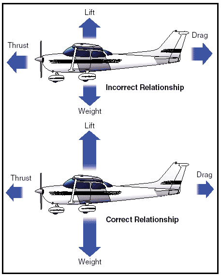
Figure 1: Relationship of forces acting on an airplane.
In steady flight, the sum of these opposing forces is equal to zero. There can be no unbalanced forces in steady, straight flight (Newton’s Third Law). This is true whether flying level or when climbing or descending. This is not the same thing as saying that the four forces are all equal. It simply means that the opposing forces are equal to, and thereby cancel the effects of, each other. Often the relationship between the four forces has been erroneously explained or illustrated in such a way that this point is obscured. Consider Figure 1 above, for example. In the upper illustration the force vectors of thrust, drag, lift, and weight appear to be equal in value. The usual explanation states (without stipulating that thrust and drag do not equal weight and lift) that thrust equals drag and lift equals weight as shown in the lower illustration. This basically true statement must be understood or it can be misleading. It should be understood that in straight, level, unaccelerated flight, it is true that the opposing lift/weight forces are equal, but they are also greater than the opposing forces of thrust/drag that are equal only to each other; not to lift/weight. To be correct about it, it must be said that in steady flight:
• The sum of all upward forces (not just lift) equals the sum of all downward forces (not just weight).
• The sum of all forward forces (not just thrust) equals the sum of all backward forces (not just drag).
This refinement of the old “thrust equals drag; lift equals weight” formula takes into account the fact that in climbs a portion of thrust, since it is directed upward, acts as if it were lift; and a portion of weight, since it is directed backward, acts as if it were drag. In glides, a portion of the weight vector is directed forward, and therefore acts as thrust. In other words, any time the flightpath of the airplane is not horizontal, lift, weight, thrust, and drag vectors must each be broken down into two components.
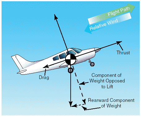
Figure 2: Force vectors during a stabilized climb.
Discussions of the preceding concepts are frequently omitted in aeronautical texts/handbooks/manuals. The reason is not that they are of no consequence, but because by omitting such discussions, the main ideas with respect to the aerodynamic forces acting upon an airplane in flight can be presented in their most essential elements without being involved in the technicalities of the aerodynamicist. In point of fact, considering only level flight, and normal climbs and glides in a steady state, it is still true that wing lift is the really important upward force, and weight is the really important downward force.
Frequently, much of the difficulty encountered in explaining the forces that act upon an airplane is largely a matter of language and its meaning. For example, pilots have long believed that an airplane climbs because of excess lift. This is not true if one is thinking in terms of wing lift alone. It is true, however, if by lift it is meant the sum total of all “upward forces.” But when referring to the “lift of thrust” or the “thrust of weight,” the definitions previously established for these forces are no longer valid and complicate matters. It is this impreciseness in language that affords the excuse to engage in arguments, largely academic, over refinements to basic principles.
Though the forces acting on an airplane have already been defined, a discussion in more detail to establish how the pilot uses them to produce controlled flight is appropriate.
Thrust
Before the airplane begins to move, thrust must be exerted. It continues to move and gain speed until thrust and drag are equal. In order to maintain a constant airspeed, thrust and drag must remain equal, just as lift and weight must be equal to maintain a constant altitude. If in level flight, the engine power is reduced, the thrust is lessened, and the airplane slows down. As long as the thrust is less than the drag, the airplane continues to decelerate until its airspeed is insufficient to support it in the air.
Likewise, if the engine power is increased, thrust becomes greater than drag and the airspeed increases. As long as the thrust continues to be greater than the drag, the airplane continues to accelerate.
When drag equals thrust, the airplane flies at a constant airspeed.
Straight-and-level flight may be sustained at speeds from very slow to very fast. The pilot must coordinate angle of attack and thrust in all speed regimes if the airplane is to be held in level flight. Roughly, these regimes can be grouped in three categories: low-speed flight, cruising flight, and high-speed flight.
When the airspeed is low, the angle of attack must be relatively high to increase lift if the balance between lift and weight is to be maintained.

Figure 3: Angle of attack at various speeds.
If thrust decreases and airspeed decreases, lift becomes less than weight and the airplane will start to descend. To maintain level flight, the pilot can increase the angle of attack an amount which will generate a lift force again equal to the weight of the airplane and while the airplane will be flying more slowly, it will still maintain level flight if the pilot has properly coordinated thrust and angle of attack.
Straight-and-level flight in the slow speed regime provides some interesting conditions relative to the equilibrium of forces, because with the airplane in a nose-high attitude, there is a vertical component of thrust that helps support the airplane. For one thing, wing loading tends to be less than would be expected. Most pilots are aware that an airplane will stall, other conditions being equal, at a slower speed with the power on than with the power off. (Induced airflow over the wings from the propeller also contributes to this.) However, if analysis is restricted to the four forces as they are usually defined, one can say that in straight-and-level slow speed flight the thrust is equal to drag, and lift is equal to weight.
During straight-and level-flight when thrust is increased and the airspeed increases, the angle of attack must be decreased. That is, if changes have been coordinated, the airplane will still remain in level flight but at a higher speed when the proper relationship between thrust and angle of attack is established.
If the angle of attack were not coordinated (decreased) with this increase of thrust, the airplane would climb. But decreasing the angle of attack modifies the lift, keeping it equal to the weight, and if properly done, the airplane still remains in level flight. Level flight at even slightly negative angles of attack is possible at very high speed. It is evident then, that level flight can be performed with any angle of attack between stalling angle and the relatively small negative angles found at high speed.
Drag
Drag in flight is of two basic types: parasite drag and induced drag. The first is called parasite because it in no way functions to aid flight, while the second is induced or created as a result of the wing developing lift.
Parasite drag is composed of two basic elements: form drag, resulting from the disruption of the streamline flow; and the resistance of skin friction.
Of the two components of parasite drag, form drag is the easier to reduce when designing an airplane. In general, a more streamlined object produces the best form to reduce parasite drag.
Skin friction is the type of parasite drag that is most difficult to reduce. No surface is perfectly smooth. Even machined surfaces, when inspected through magnification, have a ragged, uneven appearance. This rough surface will deflect the streamlines of air on the surface, causing resistance to smooth airflow. Skin friction can be minimized by employing a glossy, flat finish to surfaces, and by eliminating protruding rivet heads, roughness, and other irregularities.
Another element must be added to the consideration of parasite drag when designing an airplane. This drag combines the effects of form drag and skin friction and is called interference drag. If two objects are placed adjacent to one another, the resulting turbulence produced may be 50 to 200 percent greater than the parts tested separately.
The three elements, form drag, skin friction, and interference drag, are all computed to determine parasite drag on an airplane.
Shape of an object is a big factor in parasite drag. However, indicated airspeed is an equally important factor when speaking of parasite drag. The profile drag of a streamlined object held in a fixed position relative to the airflow increases approximately as the square of the velocity; thus, doubling the airspeed increases the drag four times, and tripling the airspeed increases the drag nine times. This relationship, however, holds good only at comparatively low subsonic speeds. At some higher airspeeds, the rate at which profile drag has been increased with speed suddenly begins to increase more rapidly.
The second basic type of drag is induced drag. It is an established physical fact that no system, which does work in the mechanical sense, can be 100 percent efficient. This means that whatever the nature of the system, the required work is obtained at the expense of certain additional work that is dissipated or lost in the system. The more efficient the system, the smaller this loss.
In level flight the aerodynamic properties of the wing produce a required lift, but this can be obtained only at the expense of a certain penalty. The name given to this penalty is induced drag. Induced drag is inherent whenever a wing is producing lift and, in fact, this type of drag is inseparable from the production of lift. Consequently, it is always present if lift is produced.
The wing produces the lift force by making use of the energy of the free airstream. Whenever the wing is producing lift, the pressure on the lower surface of the wing is greater than that on the upper surface. As a result, the air tends to flow from the high pressure area below the wingtip upward to the low pressure area above the wing. In the vicinity of the wingtips, there is a tendency for these pressures to equalize, resulting in a lateral flow outward from the underside to the upper surface of the wing. This lateral flow imparts a rotational velocity to the air at the wingtips and trails behind the wing. Therefore, flow about the wingtips will be in the form of two vortices trailing behind as the wings move on.
When the airplane is viewed from the tail, these vortices will circulate counterclockwise about the right wingtip and clockwise about the left wingtip.
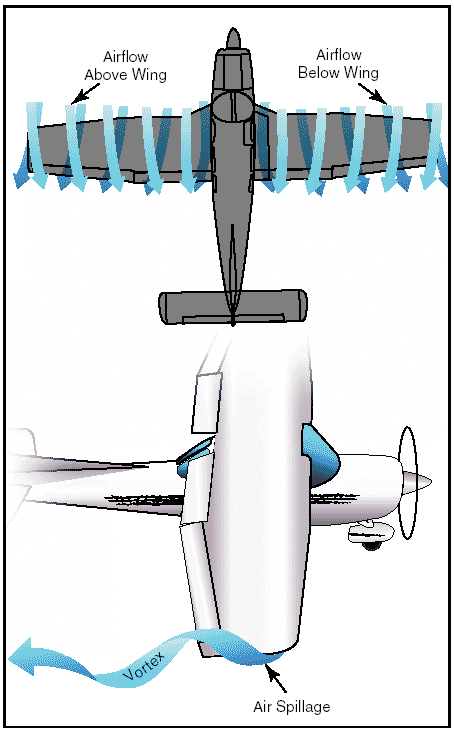
Figure 4: Wingtip vortices.
Bearing in mind the direction of rotation of these vortices, it can be seen that they induce an upward flow of air beyond the wingtip, and a downwash flow behind the wing’s trailing edge. This induced downwash has nothing in common with the downwash that is necessary to produce lift. It is, in fact, the source of induced drag. The greater the size and strength of the vortices and consequent downwash component on the net airflow over the wing, the greater the induced drag effect becomes. This downwash over the top of the wing at the tip has the same effect as bending the lift vector rearward; therefore, the lift is slightly aft of perpendicular to the relative wind, creating a rearward lift component. This is induced drag.
It should be remembered that in order to create a greater negative pressure on the top of the wing, the wing can be inclined to a higher angle of attack; also, that if the angle of attack of an asymmetrical wing were zero, there would be no pressure differential and consequently no downwash component; therefore, no induced drag. In any case, as angle of attack increases, induced drag increases proportionally.
To state this another way—the lower the airspeed the greater the angle of attack required to produce lift equal to the airplane’s weight and consequently, the greater will be the induced drag. The amount of induced drag varies inversely as the square of the airspeed.
From the foregoing discussion, it can be noted that parasite drag increases as the square of the airspeed, and induced drag varies inversely as the square of the airspeed. It can be seen that as airspeed decreases to near the stalling speed, the total drag becomes greater, due mainly to the sharp rise in induced drag. Similarly, as the airspeed reaches the terminal velocity of the airplane, the total drag again increases rapidly, due to the sharp increase of parasite drag. As seen in figure 5, at some given airspeed, total drag is at its maximum amount. This is very important in figuring the maximum endurance and range of airplanes; for when drag is at a minimum, power required to overcome drag is also at a minimum.
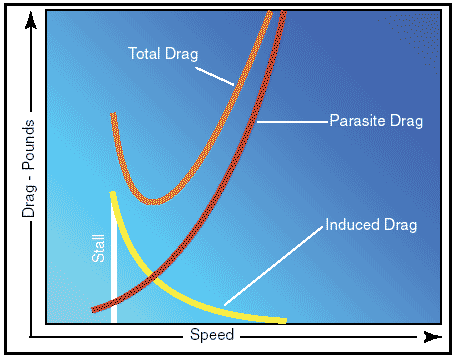
Figure 5: Drag versus speed.
To understand the effect of lift and drag on an airplane in flight, both must be combined and the lift/drag ratio considered. With the lift and drag data available for various airspeeds of the airplane in steady, unaccelerated flight, the proportions of CL (Coefficient of Lift) and CD (Coefficient of Drag) can be calculated for each specific angle of attack.
The resulting plot for lift/drag ratio with angle of attack shows that L/D increases to some maximum, then decreases at the higher lift coefficients and angles of attack, as shown in figure 6. Note that the maximum lift/drag ratio, (L/D max) occurs at one specific angle of attack and lift coefficient. If the airplane is operated in steady flight at L/D max, the total drag is at a minimum. Any angle of attack lower or higher than that for L/D max reduces the lift/drag ratio and consequently increases the total drag for a given airplane’s lift.
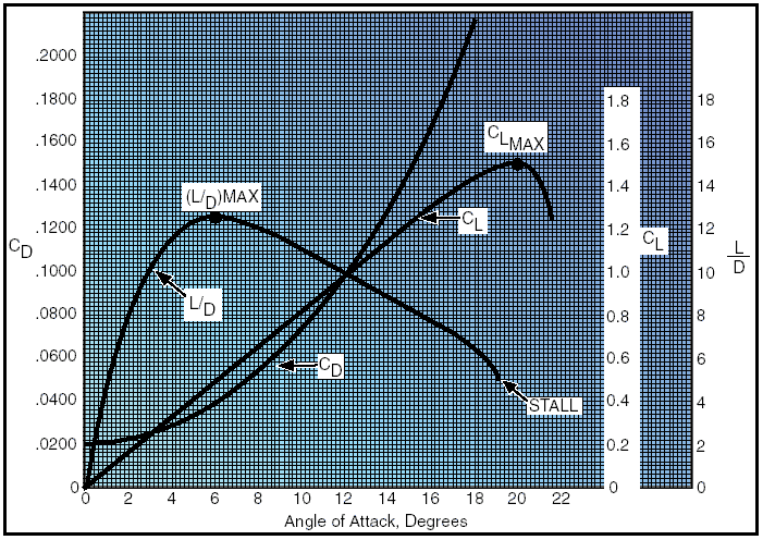
Figure 6: Lift coefficients at various angles of attack.
The location of the center of gravity (CG) is determined by the general design of each particular airplane. The designers determine how far the center of pressure (CP) will travel. They then fix the center of gravity forward of the center of pressure for the corresponding flight speed in order to provide an adequate restoring moment to retain flight equilibrium.
The configuration of an airplane has a great effect on the lift/drag ratio. The high performance sailplane may have extremely high lift/drag ratios. The supersonic fighter may have seemingly low lift/drag ratios in subsonic flight, but the airplane configurations required for supersonic flight (and high L/Ds at high Mach numbers) cause this situation.
Weight
Gravity is the pulling force that tends to draw all bodies to the center of the earth. The center of gravity (CG) may be considered as a point at which all the weight of the airplane is concentrated. If the airplane were supported at its exact center of gravity, it would balance in any attitude. It will be noted that center of gravity is of major importance in an airplane, for its position has a great bearing upon stability.
The location of the center of gravity is determined by the general design of each particular airplane. The designers determine how far the center of pressure (CP) will travel. They then fix the center of gravity forward of the center of pressure for the corresponding flight speed in order to provide an adequate restoring moment to retain flight equilibrium.
Weight has a definite relationship with lift, and thrust with drag. This relationship is simple, but important in understanding the aerodynamics of flying. Lift is the upward force on the wing acting perpendicular to the relative wind. Lift is required to counteract the airplane’s weight (which is caused by the force of gravity acting on the mass of the airplane). This weight (gravity) force acts downward through the airplane’s center of gravity. In stabilized level flight, when the lift force is equal to the weight force, the airplane is in a state of equilibrium and neither gains nor loses altitude.
If lift becomes less than weight, the airplane loses altitude. When the lift is greater than weight, the airplane gains altitude.
Lift
The pilot can control the lift. Any time the control wheel is more fore or aft, the angle of attack is changed. As angle of attack increases, lift increases (all other factors being equal). When the airplane reaches the maximum angle of attack, lift begins to diminish rapidly. This is the stalling angle of attack, or burble point.
Before proceeding further with lift and how it can be controlled, velocity must be interjected. The shape of the wing cannot be effective unless it continually keeps “attacking” new air. If an airplane is to keep flying, it must keep moving. Lift is proportional to the square of the airplane’s velocity. For example, an airplane traveling at 200 knots has four times the lift as the same airplane traveling at 100 knots, if the angle of attack and other factors remain constant.
Actually, the airplane could not continue to travel in level flight at a constant altitude and maintain the same angle of attack if the velocity is increased. The lift would increase and the airplane would climb as a result of the increased lift force. Therefore, to maintain the lift and weight forces in balance, and to keep the airplane “straight and level” (not accelerating upward) in a state of equilibrium, as velocity is increased, lift must be decreased. This is normally accomplished by reducing the angle of attack; i.e., lowering the nose. Conversely, as the airplane is slowed, the decreasing velocity requires increasing the angle of attack to maintain lift sufficient to maintain flight. There is, of course, a limit to how far the angle of attack can be increased, if a stall is to be avoided.
Therefore, it may be concluded that for every angle of attack there is a corresponding indicated airspeed required to maintain altitude in steady, unaccelerated flight—all other factors being constant. (Bear in mind this is only true if maintaining “level flight.”)
Since an airfoil will always stall at the same angle of attack, if increasing weight, lift must also be increased, and the only method for doing so is by increased velocity if the angle of attack is held constant just short of the “critical” or stalling angle of attack.
Lift and drag also vary directly with the density of the air. Density is affected by several factors: pressure, temperature, and humidity. Remember, at an altitude of 18,000 feet, the density of the air has one-half the density of air at sea level. Therefore, in order to maintain its lift at a higher altitude, an airplane must fly at a greater true airspeed for any given angle of attack.
Furthermore, warm air is less dense than cool air, and moist air is less dense than dry air. Thus, on a hot humid day, an airplane must be flown at a greater true airspeed for any given angle of attack than on a cool, dry day.
If the density factor is decreased and the total lift must equal the total weight to remain in flight, it follows that one of the other factors must be increased. The factors usually increased are the airspeed or the angle of attack, because these factors can be controlled directly by the pilot.
It should also be pointed out that lift varies directly with the wing area, provided there is no change in the wing’s planform. If the wings have the same proportion and airfoil sections, a wing with a planform area of 200 square feet lifts twice as much at the same angle of attack as a wing with an area of 100 square feet.
As can be seen, two major factors from the pilot’s viewpoint are lift and velocity because these are the two that can be controlled most readily and accurately.
Of course, the pilot can also control density by adjusting the altitude and can control wing area if the airplane happens to have flaps of the type that enlarge wing area. However, for most situations, the pilot is controlling lift and velocity to maneuver the airplane. For instance, in straight-and-level flight, cruising along at a constant altitude, altitude is maintained by adjusting lift to match the airplane’s velocity or cruise airspeed, while maintaining a state of equilibrium where lift equals weight. In an approach to landing, when the pilot wishes to land as slowly as practical, it is necessary to increase lift to near maximum to maintain lift equal to the weight of the airplane.
Wingtip vortices
The action of the airfoil that gives an airplane lift also causes induced drag. It was determined that when a wing is flown at a positive angle of attack, a pressure differential exists between the upper and lower surfaces of the wing—that is, the pressure above the wing is less than atmospheric pressure and the pressure below the wing is equal to or greater than atmospheric pressure. Since air always moves from high pressure toward low pressure, and the path of least resistance is toward the airplane’s wingtips, there is a spanwise movement of air from the bottom of the wing outward from the fuselage around the wingtips. This flow of air results in “spillage” over the wingtips, thereby setting up a whirlpool of air called a “vortex.” [Figure 4]
At the same time, the air on the upper surface of the wing has a tendency to flow in toward the fuselage and off the trailing edge. This air current forms a similar vortex at the inboard portion of the trailing edge of the wing, but because the fuselage limits the inward flow, the vortex is insignificant. Consequently, the deviation in flow direction is greatest at the wingtips where the unrestricted lateral flow is the strongest. As the air curls upward around the wingtip, it combines with the wing’s downwash to form a fast spinning trailing vortex. These vortices increase drag because of energy spent in producing the turbulence.
It can be seen, then, that whenever the wing is producing lift, induced drag occurs, and wingtip vortices are created.
Just as lift increases with an increase in angle of attack, induced drag also increases. This occurs because as the angle of attack is increased, there is a greater pressure difference between the top and bottom of the wing, and a greater lateral flow of air; consequently, this causes more violent vortices to be set up, resulting in more turbulence and more induced drag.
The intensity or strength of the wingtip vortices is directly proportional to the weight of the airplane and inversely proportional to the wingspan and speed of the airplane. The heavier and slower the airplane, the greater the angle of attack and the stronger the wingtip vortices. Thus, an airplane will create wingtip vortices with maximum strength occurring during the takeoff, climb, and landing phases of flight.
Ground effect
It is possible to fly an airplane just clear of the ground (or water) at a slightly slower airspeed than that required to sustain level flight at higher altitudes. This is the result of a phenomenon, which is better known than understood even by some experienced pilots.
When an airplane in flight gets within several feet from the ground surface, a change occurs in the threedimensional flow pattern around the airplane because the vertical component of the airflow around the wing is restricted by the ground surface. This alters the wing’s upwash, downwash, and wingtip vortices.
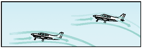
Figure 7: Ground effect changes airflow.
These general effects due to the presence of the ground are referred to as “ground effect.”
Ground effect, then, is due to the interference of the ground (or water) surface with the airflow patterns about the airplane in flight.
While the aerodynamic characteristics of the tail surfaces and the fuselage are altered by ground effects, the principal effects due to proximity of the ground are the changes in the aerodynamic characteristics of the wing. As the wing encounters ground effect and is maintained at a constant lift coefficient, there is consequent reduction in the upwash, downwash, and the wingtip vortices.
Induced drag is a result of the wing’s work of sustaining the airplane and the wing lifts the airplane simply by accelerating a mass of air downward. It is true that reduced pressure on top of an airfoil is essential to lift, but that is but one of the things that contributes to the overall effect of pushing an air mass downward. The more downwash there is, the harder the wing is pushing the mass of air down. At high angles of attack, the amount of induced drag is high and since this corresponds to lower airspeeds in actual flight, it can be said that induced drag predominates at low speed.
However, the reduction of the wingtip vortices due to ground effect alters the spanwise lift distribution and reduces the induced angle of attack and induced drag. Therefore, the wing will require a lower angle of attack in ground effect to produce the same lift coefficient or, if a constant angle of attack is maintained, an increase in lift coefficient will result.
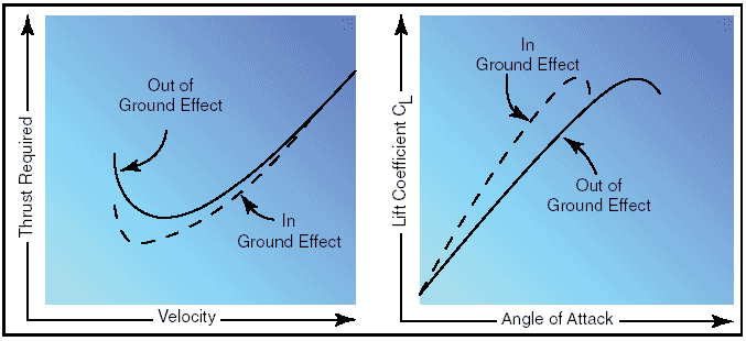
Figure 8: Ground effect changes drag and lift.
Ground effect also will alter the thrust required versus velocity. Since induced drag predominates at low speeds, the reduction of induced drag due to ground effect will cause the most significant reduction of thrust required (parasite plus induced drag) at low speeds.
The reduction in induced flow due to ground effect causes a significant reduction in induced drag but causes no direct effect on parasite drag. As a result of the reduction in induced drag, the thrust required at low speeds will be reduced.
Due to the change in upwash, downwash, and wingtip vortices, there may be a change in position (installation) error of the airspeed system, associated with ground effect. In the majority of cases, ground effect will cause an increase in the local pressure at the static source and produce a lower indication of airspeed and altitude. Thus, the airplane may be airborne at an indicated airspeed less than that normally required.
In order for ground effect to be of significant magnitude, the wing must be quite close to the ground. One of the direct results of ground effect is the variation of induced drag with wing height above the ground at a constant lift coefficient. When the wing is at a height equal to its span, the reduction in induced drag is only 1.4 percent. However, when the wing is at a height equal to one-fourth its span, the reduction in induced drag is 23.5 percent and, when the wing is at a height equal to one-tenth its span, the reduction in induced drag is 47.6 percent. Thus, a large reduction in induced drag will take place only when the wing is very close to the ground. Because of this variation, ground effect is most usually recognized during the liftoff for takeoff or just prior to touchdown when landing.
During the takeoff phase of flight, ground effect produces some important relationships. The airplane leaving ground effect after takeoff encounters just the reverse of the airplane entering ground effect during landing; i.e., the airplane leaving ground effect will:
• Require an increase in angle of attack to maintain the same lift coefficient.
• Experience an increase in induced drag and thrust required.
• Experience a decrease in stability and a nose-up change in moment.
• Produce a reduction in static source pressure and increase in indicated airspeed.
These general effects should point out the possible danger in attempting takeoff prior to achieving the recommended takeoff speed. Due to the reduced drag in ground effect, the airplane may seem capable of takeoff well below the recommended speed.
However, as the airplane rises out of ground effect with a deficiency of speed, the greater induced drag may result in very marginal initial climb performance.
In the extreme conditions such as high gross weight, high density altitude, and high temperature, a deficiency of airspeed during takeoff may permit the airplane to become airborne but be incapable of flying out of ground effect. In this case, the airplane may become airborne initially with a deficiency of speed, and then settle back to the runway. It is important that no attempt be made to force the airplane to become airborne with a deficiency of speed; the recommended takeoff speed is necessary to provide adequate initial climb performance. For this reason, it is imperative that a definite climb be established before retracting the landing gear or flaps.
During the landing phase of flight, the effect of proximity to the ground also must be understood and appreciated. If the airplane is brought into ground effect with a constant angle of attack, the airplane will experience an increase in lift coefficient and a reduction in the thrust required. Hence, a “floating” effect may occur. Because of the reduced drag and power off deceleration in ground effect, any excess speed at the point of flare may incur a considerable “float” distance. As the airplane nears the point of touchdown, ground effect will be most realized at altitudes less than the wingspan. During the final phases of the approach as the airplane nears the ground, a reduced power setting is necessary or the reduced thrust required would allow the airplane to climb above the desired glidepath.
Aerodynamic forces in flight maneuvers
Forces in turns
If an airplane were viewed in straight-and-level flight from the rear, and if the forces acting on the airplane actually could be seen, two forces (lift and weight) would be apparent, and if the airplane were in a bank it would be apparent that lift did not act directly opposite to the weight—it now acts in the direction of the bank.
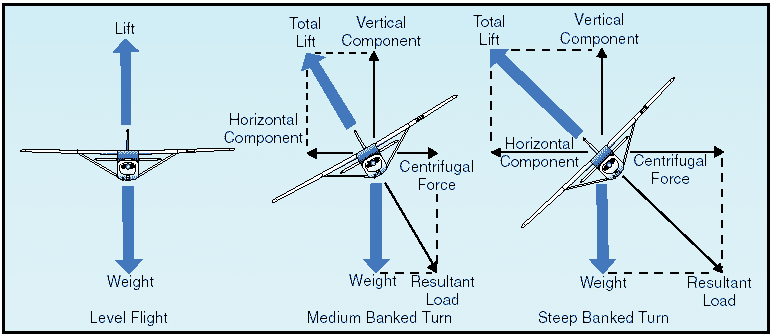
Figure 9: Forces during normal coordinated turn.
The fact that when the airplane banks, lift acts inward toward the center of the turn, as well as upward, is one of the basic truths to remember in the consideration of turns.
An object at rest or moving in a straight line will remain at rest or continue to move in a straight line until acted on by some other force. An airplane, like any moving object, requires a sideward force to make it turn. In a normal turn, this force is supplied by banking the airplane so that lift is exerted inward as well as upward. The force of lift during a turn is separated into two components at right angles to each other. One component, which acts vertically and opposite to the weight (gravity), is called the “vertical component of lift.” The other, which acts horizontally toward the center of the turn, is called the “horizontal component of lift,” or centripetal force. The horizontal component of lift is the force that pulls the airplane from a straight flightpath to make it turn. Centrifugal force is the “equal and opposite reaction” of the airplane to the change in direction and acts equal and opposite to the horizontal component of lift. This explains why, in a correctly executed turn, the force that turns the airplane is not supplied by the rudder.
An airplane is not steered like a boat or an automobile; in order for it to turn, it must be banked. If the airplane is not banked, there is no force available that will cause it to deviate from a straight flightpath.
Conversely, when an airplane is banked, it will turn, provided it is not slipping to the inside of the turn.
Good directional control is based on the fact that the airplane will attempt to turn whenever it is banked.
This fact should be borne in mind at all times, particularly while attempting to hold the airplane in straight-and-level flight.
Merely banking the airplane into a turn produces no change in the total amount of lift developed.
However, as was pointed out, the lift during the bank is divided into two components: one vertical and the other horizontal. This division reduces the amount of lift which is opposing gravity and actually supporting the airplane’s weight; consequently, the airplane loses altitude unless additional lift is created. This is done by increasing the angle of attack until the vertical component of lift is again equal to the weight.
Since the vertical component of lift decreases as the bank angle increases, the angle of attack must be progressively increased to produce sufficient vertical lift to support the airplane’s weight. The fact that the vertical component of lift must be equal to the weight to maintain altitude is an important fact to remember when making constant altitude turns.
At a given airspeed, the rate at which an airplane turns depends upon the magnitude of the horizontal component of lift. It will be found that the horizontal component of lift is proportional to the angle of bank—that is, it increases or decreases respectively as the angle of bank increases or decreases. It logically follows then, that as the angle of bank is increased the horizontal component of lift increases, thereby increasing the rate of turn. Consequently, at any given airspeed the rate of turn can be controlled by adjusting the angle of bank.
To provide a vertical component of lift sufficient to hold altitude in a level turn, an increase in the angle of attack is required. Since the drag of the airfoil is directly proportional to its angle of attack, induced drag will increase as the lift is increased. This, in turn, causes a loss of airspeed in proportion to the angle of bank; a small angle of bank results in a small reduction in airspeed and a large angle of bank results in a large reduction in airspeed.
Additional thrust (power) must be applied to prevent a reduction in airspeed in level turns; the required amount of additional thrust is proportional to the angle of bank.
To compensate for added lift, which would result if the airspeed were increased during a turn, the angle of attack must be decreased, or the angle of bank increased, if a constant altitude were to be maintained.
If the angle of bank were held constant and the angle of attack decreased, the rate of turn would decrease. Therefore, in order to maintain a constant rate of turn as the airspeed is increased, the angle of attack must remain constant and the angle of bank increased.
It must be remembered that an increase in airspeed results in an increase of the turn radius and that centrifugal force is directly proportional to the radius of the turn. In a correctly executed turn, the horizontal component of lift must be exactly equal and opposite to the centrifugal force. Therefore, as the airspeed is increased in a constant rate level turn, the radius of the turn increases. This increase in the radius of turn causes an increase in the centrifugal force, which must be balanced by an increase in the horizontal component of lift, which can only be increased by increasing the angle of bank.
In a slipping turn, the airplane is not turning at the rate appropriate to the bank being used, since the airplane is yawed toward the outside of the turning flightpath. The airplane is banked too much for the rate of turn, so the horizontal lift component is greater than the centrifugal force.
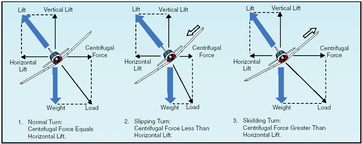
Figure 10: Normal, sloping, and skidding turns.
Equilibrium between the horizontal lift component and centrifugal force is reestablished either by decreasing the bank, increasing the rate of turn, or a combination of the two changes.
A skidding turn results from an excess of centrifugal force over the horizontal lift component, pulling the airplane toward the outside of the turn. The rate of turn is too great for the angle of bank. Correction of a skidding turn thus involves a reduction in the rate of turn, an increase in bank, or a combination of the two changes.
To maintain a given rate of turn, the angle of bank must be varied with the airspeed. This becomes particularly important in high-speed airplanes. For instance, at 400 miles per hour (m.p.h.), an airplane must be banked approximately 44° to execute a standard rate turn (3° per second). At this angle of bank, only about 79 percent of the lift of the airplane comprises the vertical component of the lift; the result is a loss of altitude unless the angle of attack is increased sufficiently to compensate for the loss of vertical lift.
Forces in climbs
For all practical purposes, the wing’s lift in a steady state normal climb is the same as it is in a steady level flight at the same airspeed. Though the airplane’s flightpath has changed when the climb has been established, the angle of attack of the wing with respect to the inclined flightpath reverts to practically the same values, as does the lift.
There is an initial momentary change, however, as shown in figure 11. During the transition from straight-and-level flight to a climb, a change in lift occurs when back elevator pressure is first applied.
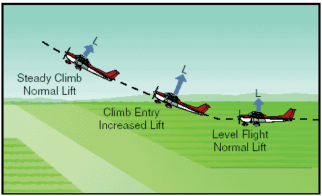
Figure 11: Changes in lift during climb entry.
Raising the airplane’s nose increases the angle of attack and momentarily increases the lift. Lift at this moment is now greater than weight and starts the airplane climbing. After the flightpath is stabilized on the upward incline, the angle of attack and lift again revert to about the level flight values.
If the climb is entered with no change in power setting, the airspeed gradually diminishes because the thrust required to maintain a given airspeed in level flight is insufficient to maintain the same airspeed in a climb. When the flightpath is inclined upward, a component of the airplane’s weight acts in the same direction as, and parallel to, the total drag of the airplane, thereby increasing the total effective drag. Consequently, the total drag is greater than the power, and the airspeed decreases. The reduction in airspeed gradually results in a corresponding decrease in drag until the total drag (including the component of weight acting in the same direction) equals the thrust.
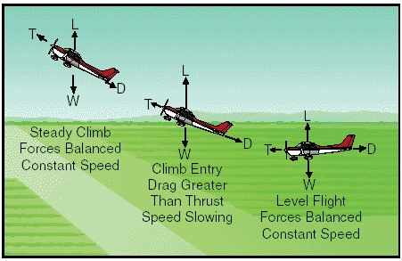
Figure 12: Changes in speed during climb entry.
Due to momentum, the change in airspeed is gradual, varying considerably with differences in airplane size, weight, total drag, and other factors.
Generally, the forces of thrust and drag, and lift and weight, again become balanced when the airspeed stabilizes but at a value lower than in straight-and-level flight at the same power setting.
Since in a climb the airplane’s weight is not only acting downward but rearward along with drag, additional power is required to maintain the same airspeed as in level flight. The amount of power depends on the angle of climb. When the climb is established so steep that there is insufficient power available, a slower speed results. It will be seen then that the amount of reserve power determines the climb performance of the airplane.
Forces in descents
As in climbs, the forces acting on the airplane go through definite changes when a descent is entered from straight-and-level flight. The analysis here is that of descending at the same power as used in straight-and-level flight.
When forward pressure is applied to the elevator control to start descending, or the airplane’s nose is allowed to pitch down, the angle of attack is decreased and, as a result, the lift of the airfoil is reduced. This reduction in total lift and angle of attack is momentary and occurs during the time the flightpath changes downward. The change to a downward flightpath is due to the lift momentarily becoming less than the weight of the airplane as the angle of attack is reduced. This imbalance between lift and weight causes the airplane to follow a descending flightpath with respect to the horizontal flightpath of straight-and-level flight. When the flightpath is in a steady descent, the airfoil’s angle of attack again approaches the original value, and lift and weight will again become stabilized. From the time the descent is started until it is stabilized, the airspeed will gradually increase. This is due to a component of weight now acting forward along the flightpath, similar to the manner it acted rearward in a climb. The overall effect is that of increased power or thrust, which in turn causes the increase in airspeed associated with descending at the same power as used in level flight.
To descend at the same airspeed as used in straightand-level flight, obviously, the power must be reduced as the descent is entered. The component of weight acting forward along the flightpath will increase as the angle of rate of descent increases and conversely, will decrease as the angle of rate of descent decreases. Therefore, the amount of power reduction required for a descent at the same speed as cruise will be determined by the steepness of the descent.
Stalls
An airplane will fly as long as the wing is creating sufficient lift to counteract the load imposed on it. When the lift is completely lost, the airplane stalls.
Remember, the direct cause of every stall is an excessive angle of attack. There are any number of flight maneuvers which may produce an increase in the angle of attack, but the stall does not occur until the angle of attack becomes excessive.
It must be emphasized that the stalling speed of a particular airplane is not a fixed value for all flight situations. However, a given airplane will always stall at the same angle of attack regardless of airspeed, weight, load factor, or density altitude. Each airplane has a particular angle of attack where the airflow separates from the upper surface of the wing and the stall occurs. This critical angle of attack varies from 16° to 20° depending on the airplane’s design. But each airplane has only one specific angle of attack where the stall occurs.
There are three situations in which the critical angle of attack can be exceeded: in low-speed flying, in high-speed flying, and in turning flight.
The airplane can be stalled in straight-and-level flight by flying too slowly. As the airspeed is being decreased, the angle of attack must be increased to retain the lift required for maintaining altitude. The slower the airspeed becomes, the more the angle of attack must be increased. Eventually, an angle of attack is reached which will result in the wing not producing enough lift to support the airplane and it will start settling. If the airspeed is reduced further, the airplane will stall, since the angle of attack has exceeded the critical angle and the airflow over the wing is disrupted.
It must be reemphasized here that low speed is not necessary to produce a stall. The wing can be brought into an excessive angle of attack at any speed. For example, take the case of an airplane which is in a dive with an airspeed of 200 knots when suddenly the pilot pulls back sharply on the elevator control.
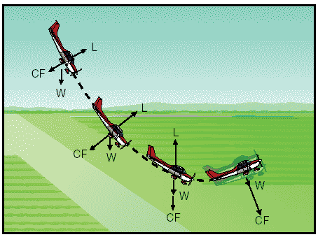
Figure 13: Forces exerted when pulling out of a dive.
Because of gravity and centrifugal force, the airplane could not immediately alter its flightpath but would merely change its angle of attack abruptly from quite low to very high.
Since the flightpath of the airplane in relation to the oncoming air determines the direction of the relative wind, the angle of attack is suddenly increased, and the airplane would quickly reach the stalling angle at a speed much greater than the normal stall speed.
Similarly, the stalling speed of an airplane is higher in a level turn than in straight-and-level flight.
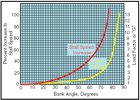
Figure 14: Increase in stall speed and load factor.
This is because centrifugal force is added to the airplane’s weight, and the wing must produce sufficient additional lift to counterbalance the load imposed by the combination of centrifugal force and weight. In a turn, the necessary additional lift is acquired by applying back pressure to the elevator control. This increases the wing’s angle of attack, and results in increased lift. The angle of attack must increase as the bank angle increases to counteract the increasing load caused by centrifugal force. If at any time during a turn the angle of attack becomes excessive, the airplane will stall.
At this point, the action of the airplane during a stall should be examined. To balance the airplane aerodynamically, the center of lift is normally located aft of the center of gravity. Although this makes the airplane inherently “nose heavy,” downwash on the horizontal stabilizer counteracts this condition. It can be seen then, that at the point of stall when the upward force of the wing’s lift and the downward tail force cease, an unbalanced condition exists. This allows the airplane to pitch down abruptly, rotating about its center of gravity.
During this nose-down attitude, the angle of attack decreases and the airspeed again increases; hence, the smooth flow of air over the wing begins again, lift returns, and the airplane is again flying.
However, considerable altitude may be lost before this cycle is complete.