|
|
| | AIRCRAFT PROPELLER CONTROL AND OPERATION |
| | | Control and Operation (page 1) | | | Propeller Control | basic requirement: For flight operation, an engine is demanded to deliver power within a relatively narrow band of operating rotation speeds. During flight, the speed-sensitive governor of the propeller automatically controls the blade angle as required to maintain a constant r.p.m. of the engine.
Three factors tend to vary the r.p.m. of the engine during operation. These factors are power, airspeed, and air density. If the r.p.m. is to maintain constant, the blade angle must vary directly with power, directly with airspeed, and inversely with air density. The speed-sensitive governor provides the means by which the propeller can adjust itself automatically to varying power and flight conditions while converting the power to thrust. | | | Fundamental Forces : Three fundamental forces are used to control blade angle . These forces are:
1. Centrifugal twisting moment, centrifugal force acting on a rotating blade which tends at all times to move the blade into low pitch.
2. Oil at engine pressure on the outboard piston side, which supplements the centrifugal twisting moment toward low pitch.
3. Propeller Governor oil on the inboard piston side, which balances the first two forces and move the blades toward high pitch
Counterweight assembly (this is only for counterweight propeller) which attached to the blades , the centrifugal forces of the counterweight will move the blades to high pitch setting | | | Constant Speed, Counterweight Propellers
The Counterweight type propeller may be used to operate either as a controllable or constant speed propeller. The hydraulic counterweight propeller consists of a hub assembly, blade assembly, cylinder assembly, and counterweight assembly.
The counterweight assembly on the propeller is attached to the blades and moves with them. The centrifugal forces obtained from rotating counterweights move the blades to high angle setting. The centrifugal force of the counterweight assembly is depended on the rotational speed of the propellers r.p.m. The propeller blades have a definite range of angular motion by an adjusting for high and low angle on the counterweight brackets.
Controllable : the operator will select either low blade angle or high blade angle by two-way valve which permits engine oil to flow into or drain from the propeller.

Constant Speed : If an engine driven governor is used, the propeller will operate as a constant speed. The propeller and engine speed will be maintained constant at any r.p.m. setting within the operating range of the propeller.
 | | | Governor Operation (Constant speed with counterweight ) the Governor supplies and controls the flow of oil to and from the propeller. The engine driven governor receives oil from the engine lubricating system and boost its pressure to that required to operate the pitch-changing mechanism. It consists essentially of :
1. A gear pump to increase the pressure of the engine oil to the pressure required for propeller operation.
2. A relief valve system which regulates the operating pressure in the governor.
3. A pilot valve actuated by flyweights which control the flow of oil through the governor
4. The speeder spring provides a mean by which the initial load on the pilot valve can be changed through the rack and pulley arrangement which controlled by pilot.
The governor maintains the required balance between all three control forces by metering to, or drain from, the inboard side of the propeller piston to maintain the propeller blade angle for constant speed operation.
The governor operates by means of flyweights which control the position of a pilot valve. When the propeller r.p.m. is below that for which the governor is set through the speeder spring by pilot , the governor flyweight move inward due to less centrifugal force act on flyweight than compression of speeder spring. If the propeller r.p.m. is higher than setting , the flyweight will move outward due to flyweight has more centrifugal force than compression of speeder spring . During the flyweight moving inward or outward , the pilot valve will move and directs engine oil pressure to the propeller cylinder through the engine propeller shaft. | | | 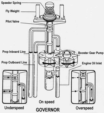 | | | Principles of Operation (Constant Speed with Counterweight Propellers)
The changes in the blades angle of a typical constant speed with counterweight propellers are accomplished by the action of two forces, one is hydraulic and the other is mechanical.
1. The cylinder is moved by oil flowing into it and opposed by centrifugal force of counterweight. This action moves the counterweight and the blades to rotate toward the low angle positon.
2. When the oil allowed to drain from the cylinder , the centrifugal force of counterweights take effect and the blades are turned toward the high angle position.
3. The constant speed control of the propeller is an engine driven governor of the flyweight type. | | |
| | |
|
| | | |