Auxiliary Aircraft Systems
Electrical system
Airplanes are equipped with either a 14- or 28-volt direct-current electrical system. A basic airplane electrical system consists of the following components:
- Alternator/generator
- Battery
- Master/battery switch
- Alternator/generator switch
- Bus bar, fuses, and circuit breakers
- Voltage regulator
- Ammeter/loadmeter
- Associated electrical wiring
Engine-driven alternators or generators supply electric current to the electrical system. They also maintain a sufficient electrical charge in the battery. Electrical energy stored in a battery provides a source of electrical power for starting the engine and a limited supply of electrical power for use in the event the alternator or generator fails.
Most direct current generators will not produce a sufficient amount of electrical current at low engine r.p.m. to operate the entire electrical system. Therefore, during operations at low engine r.p.m., the electrical needs must be drawn from the battery, which can quickly be depleted.
Alternators have several advantages over generators.
Alternators produce sufficient current to operate the entire electrical system, even at slower engine speeds, by producing alternating current, which is converted to direct current. The electrical output of an alternator is more constant throughout a wide range of engine speeds.
Some airplanes have receptacles to which an external ground power unit (GPU) may be connected to provide electrical energy for starting. These are very useful, especially during cold weather starting. Follow the manufacturer´s recommendations for engine starting using a GPU.
The electrical system is turned on or off with a master switch. Turning the master switch to the ON position provides electrical energy to all the electrical equipment circuits with the exception of the ignition system. Equipment that commonly uses the electrical system for its source of energy includes:
- Position lights
- Anticollision lights
- Landing lights
- Taxi lights
- Interior cabin lights
- Instrument lights
- Radio equipment
- Turn indicator
- Fuel gauges
- Electric fuel pump
- Stall warning system
- Pitot heat
- Starting motor
Many airplanes are equipped with a battery switch that controls the electrical power to the airplane in a manner similar to the master switch. In addition, an alternator switch is installed which permits the pilot to exclude the alternator from the electrical system in the event of alternator failure.
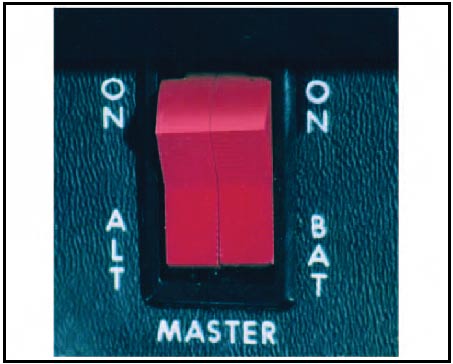
Figure 1: On this master switch, the left half is for the alternator and the right half is for the battery.
With the alternator half of the switch in the OFF position, the entire electrical load is placed on the battery. Therefore, all nonessential electrical equipment should be turned off to conserve battery power.
A bus bar is used as a terminal in the airplane electrical system to connect the main electrical system to the equipment using electricity as a source of power. This simplifies the wiring system and provides a common point from which voltage can be distributed throughout the system.
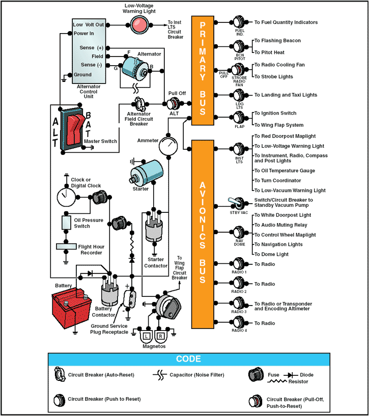
Figure 2: Electrical system schematic.
Fuses or circuit breakers are used in the electrical system to protect the circuits and equipment from electrical overload. Spare fuses of the proper amperage limit should be carried in the airplane to replace defective or blown fuses. Circuit breakers have the same function as a fuse but can be manually reset, rather than replaced, if an overload condition occurs in the electrical system.
Placards at the fuse or circuit breaker panel identify the circuit by name and show the amperage limit.
An ammeter is used to monitor the performance of the airplane electrical system. The ammeter shows if the alternator/generator is producing an adequate supply of electrical power. It also indicates whether or not the battery is receiving an electrical charge.
Ammeters are designed with the zero point in the center of the face and a negative or positive indication on either side.
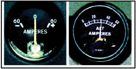
Figure 3: Ammeter and loadmeter.
When the pointer of the ammeter on the left is on the plus side, it shows the charging rate of the battery. A minus indication means more current is being drawn from the battery than is being replaced. A full-scale minus deflection indicates a malfunction of the alternator/generator. A full-scale positive deflection indicates a malfunction of the regulator. In either case, consult the AFM or POH for appropriate action to be taken.
Not all airplanes are equipped with an ammeter. Some have a warning light that, when lighted, indicates a discharge in the system as a generator/alternator malfunction. Refer to the AFM or POH for appropriate action to be taken.
Another electrical monitoring indicator is a loadmeter. This type of gauge, illustrated on the right in figure 3, has a scale beginning with zero and shows the load being placed on the alternator/generator. The loadmeter reflects the total percentage of the load placed on the generating capacity of the electrical system by the electrical accessories and battery. When all electrical components are turned off, it reflects only the amount of charging current demanded by the battery.
A voltage regulator controls the rate of charge to the battery by stabilizing the generator or alternator electrical output. The generator/alternator voltage output should be higher than the battery voltage. For example, a 12-volt battery would be fed by a generator/alternator system of approximately 14 volts.The difference in voltage keeps the battery charged.
Hydraulic systems
There are multiple applications for hydraulic use in airplanes, depending on the complexity of the airplane.
For example, hydraulics are often used on small airplanes to operate wheel brakes, retractable landing gear, and some constant-speed propellers. On large airplanes, hydraulics are used for flight control surfaces, wing flaps, spoilers, and other systems.
A basic hydraulic system consists of a reservoir, pump (either hand, electric, or engine driven), a filter to keep the fluid clean, selector valve to control the direction of flow, relief valve to relieve excess pressure, and an actuator.
The hydraulic fluid is pumped through the system to an actuator or servo. Servos can be either single-acting or double-acting servos based on the needs of the system.
This means that the fluid can be applied to one or both sides of the servo, depending on the servo type, and therefore provides power in one direction with a single-acting servo. A servo is a cylinder with a piston inside that turns fluid power into work and creates the power needed to move an aircraft system or flight control. The selector valve allows the fluid direction to be controlled. This is necessary for operations like the extension and retraction of landing gear where the fluid must work in two different directions. The relief valve provides an outlet for the system in the event of excessive fluid pressure in the system. Each system incorporates different components to meet the individual needs of different aircraft.
A mineral-based fluid is the most widely used type for small airplanes. This type of hydraulic fluid, which is a kerosene-like petroleum product, has good lubricating properties, as well as additives to inhibit foaming and prevent the formation of corrosion. It is quite stable chemically, has very little viscosity change with temperature, and is dyed for identification. Since several types of hydraulic fluids are commonly used, make sure your airplane is serviced with the type specified by the manufacturer. Refer to the AFM, POH, or the Maintenance Manual.
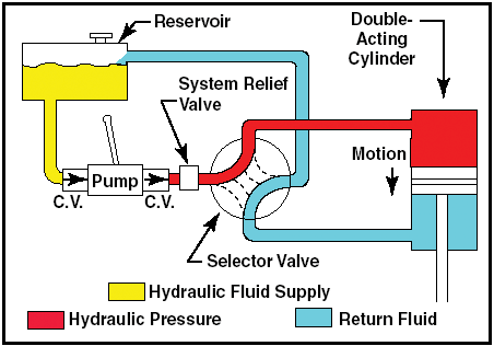
Figure 4: Basic hydraulic system.
Landing gear
The landing gear forms the principal support of the airplane on the surface. The most common type of landing gear consists of wheels, but airplanes can also be equipped with floats for water operations, or skis for landing on snow.
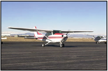
Figure 5: The landing gear supports the airplane during the takeoff run, landing, taxiing, and when parked.
The landing gear on small airplanes consists of three wheels - two main wheels, one located on each side of the fuselage, and a third wheel, positioned either at the front or rear of the airplane. Landing gear employing a rear-mounted wheel is called a conventional landing gear. Airplanes with conventional landing gear are often referred to as tailwheel airplanes. When the third wheel is located on the nose, it is called a nosewheel, and the design is referred to as a tricycle gear. A steerable nosewheel or tailwheel permits the airplane to be controlled throughout all operations while on the ground.
Tricycle landing gear airplanes
A tricycle gear airplane has three main advantages:
- It allows more forceful application of the brakes during landings at high speeds without resulting in the airplane nosing over.
- It permits better forward visibility for the pilot during takeoff, landing, and taxiing.
- It tends to prevent ground looping (swerving) by providing more directional stability during ground operation since the airplane´s center of gravity (CG) is forward of the main wheels. The forward CG, therefore, tends to keep the airplane moving forward in a straight line rather than ground looping.
Nosewheels are either steerable or castering. Steerable nosewheels are linked to the rudders by cables or rods, while castering nosewheels are free to swivel. In both cases, you steer the airplane using the rudder pedals.
However, airplanes with a castering nosewheel may require you to combine the use of the rudder pedals with independent use of the brakes.
Tailwheel landing gear airplanes
On tailwheel airplanes, two main wheels, which are attached to the airframe ahead of its center of gravity, support most of the weight of the structure, while a tailwheel at the very back of the fuselage provides a third point of support. This arrangement allows adequate ground clearance for a larger propeller and is more desirable for operations on unimproved fields.
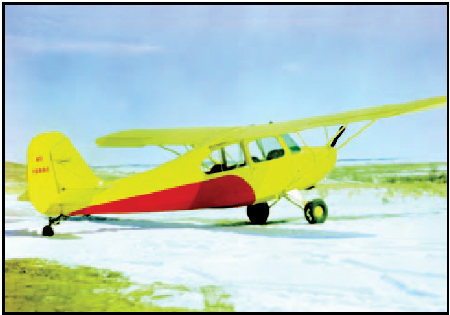
Figure 6: Tailwheel landing gear.
The main drawback with the tailwheel landing gear is that the center of gravity is behind the main gear. This makes directional control more difficult while on the ground. If you allow the airplane to swerve while rolling on the ground at a speed below that at which the rudder has sufficient control, the center of gravity will attempt to get ahead of the main gear. This may cause the airplane to ground loop.
Another disadvantage for tailwheel airplanes is the lack of good forward visibility when the tailwheel is on or near the surface. Because of the associated hazards, specific training is required in tailwheel airplanes.
Fixed and retractable landing gear
Landing gear can also be classified as either fixed or retractable. A fixed gear always remains extended and has the advantage of simplicity combined with low maintenance. A retractable gear is designed to streamline the airplane by allowing the landing gear to be stowed inside the structure during cruising flight.
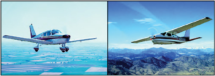
Figure 7: Fixed and retractable gear airplanes.
Brakes
Airplane brakes are located on the main wheels and are applied by either a hand control or by foot pedals (toe or heel). Foot pedals operate independently and allow for differential braking. During ground operations, differential braking can supplement nosewheel/tailwheel steering.
Autopilot
Autopilots are designed to control the aircraft and help reduce the pilot´s workload. The limitations of the autopilot depend on the complexity of the system. The common features available on an autopilot are altitude and heading hold. More advanced systems may include a vertical speed and/or indicated airspeed hold mode. Most autopilot systems are coupled to navigational aids.
An autopilot system consists of servos that actuate the flight controls. The number and location of these servos depends on the complexity of the system. For example, a single-axis autopilot controls the aircraft about the longitudinal axis and a servo actuates the ailerons. A three-axis autopilot controls the aircraft about the longitudinal, lateral, and vertical axes; and three different servos actuate the ailerons, the elevator, and the rudder.
The autopilot system also incorporates a disconnect safety feature to automatically or manually disengage the system. Autopilots can also be manually overridden. Because autopilot systems differ widely in their operation, refer to the autopilot operating instructions in the AFM or POH.
Ice control systems
Ice control systems installed on aircraft consist of anti-ice and de-ice equipment. Anti-icing equipment is designed to prevent the formation of ice, while de-icing equipment is designed to remove ice once it has formed. Ice control systems protect the leading edge of wing and tail surfaces, pitot and static port openings, fuel tank vents, stall warning devices, windshields, and propeller blades. Ice detection lighting may also be installed on some airplanes to determine the extent of structural icing during night flights. Since many airplanes are not certified for flight in icing conditions, refer to the AFM or POH for details.
Airfoil ice control
Inflatable de-icing boots consist of a rubber sheet bonded to the leading edge of the airfoil. When ice builds up on the leading edge, an engine-driven pneumatic pump inflates the rubber boots. Some turboprop aircraft divert engine bleed air to the wing to inflate the rubber boots. Upon inflation, the ice is cracked and should fall off the leading edge of the wing. De-icing boots are controlled from the cockpit by a switch and can be operated in a single cycle or allowed to cycle at automatic, timed intervals. It is important that de-icing boots are used in accordance with the manufacturer´s recommendations. If they are allowed to cycle too often, ice can form over the contour of the boot and render the boots ineffective.
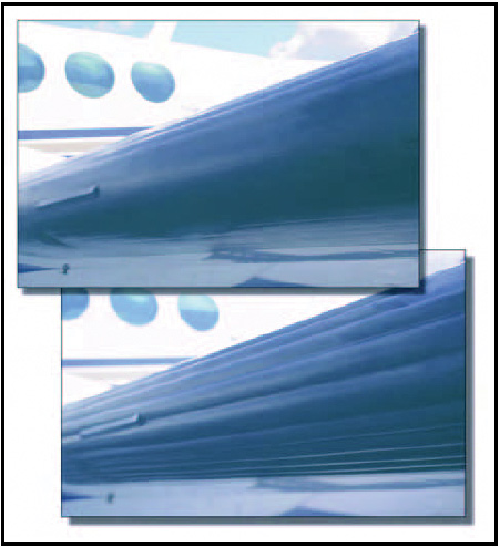
Figure 8: De-icing boots on the leading edge of the wing.
Many de-icing boot systems use the instrument system suction gauge and a pneumatic pressure gauge to indicate proper boot operation. These gauges have range markings that indicate the operating limits for boot operation. Some systems may also incorporate an annunciator light to indicate proper boot operation.
Proper maintenance and care of de-icing boots is important for continued operation of this system. They need to be carefully inspected prior to a flight.
Another type of leading edge protection is the thermal anti-ice system installed on airplanes with turbine engines. This system is designed to prevent the buildup of ice by directing hot air from the compressor section of the engine to the leading edge surfaces. The system is activated prior to entering icing conditions. The hot air heats the leading edge sufficiently to prevent the formation of ice.
An alternate type of leading edge protection that is not as common as thermal anti-ice and de-icing boots is known as a weeping wing. The weeping-wing design uses small holes located in the leading edge of the wing. A chemical mixture is pumped to the leading edge and weeps out through the holes to prevent the formation and buildup of ice.
Windscreen ice control
There are two main types of windscreen anti-ice systems. The first system directs a flow of alcohol to the windscreen. By using it early enough, the alcohol will prevent ice from building up on the windshield.
The rate of alcohol flow can be controlled by a dial in the cockpit according to procedures recommended by the airplane manufacturer.
Another effective method of anti-icing equipment is the electric heating method. Small wires or other conductive material is imbedded in the windscreen.
The heater can be turned on by a switch in the cockpit, at which time electrical current is passed across the shield through the wires to provide sufficient heat to prevent the formation of ice on the windscreen. The electrical current can cause compass deviation errors; in some cases, as much as 40°. The heated windscreen should only be used during flight. Do not leave it on during ground operations, as it can overheat and cause damage to the windscreen.
Propeller ice control
Propellers are protected from icing by use of alcohol or electrically heated elements. Some propellers are equipped with a discharge nozzle that is pointed toward the root of the blade. Alcohol is discharged from the nozzles, and centrifugal force makes the alcohol flow down the leading edge of the blade. This prevents ice from forming on the leading edge of the propeller.
Propellers can also be fitted with propeller anti-ice boots. The propeller boot is divided into two sections—the inboard and the outboard sections. The boots are grooved to help direct the flow of alcohol, and they are also imbedded with electrical wires that carry current for heating the propeller. The prop anti-ice system can be monitored for proper operation by monitoring the prop anti-ice ammeter. During the preflight inspection, check the propeller boots for proper operation. If a boot fails to heat one blade, an unequal blade loading can result, and may cause severe propeller vibration.
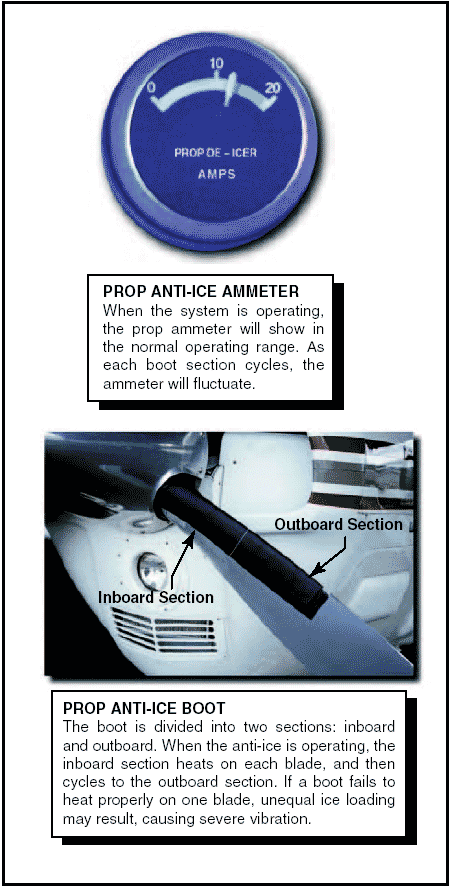
Figure 9: Prop ammeter and anti-ice boots.
Other ice control systems
Pitot and static ports, fuel vents, stall-warning sensors, and other optional equipment may be heated by electrical elements. Operational checks of the electrically heated systems are to be checked in accordance with the AFM or POH.
Operation of aircraft anti-icing and de-icing systems should be checked prior to encountering icing conditions. Encounters with structural ice require immediate remedial action. Anti-icing and de-icing equipment is not intended to sustain long-term flight in icing conditions.
Pressurized airplanes
When an airplane is flown at a high altitude, it consumes less fuel for a given airspeed than it does for the same speed at a lower altitude. In other words, the airplane is more efficient at a high altitude. In addition, bad weather and turbulence may be avoided by flying in the relatively smooth air above the storms. Because of the advantages of flying at high altitudes, many modern general aviation-type airplanes are being designed to operate in that environment. It is important that pilots transitioning to such sophisticated equipment be familiar with at least the basic operating principles.
A cabin pressurization system accomplishes several functions in providing adequate passenger comfort and safety. It maintains a cabin pressure altitude of approximately 8,000 feet at the maximum designed cruising altitude of the airplane, and prevents rapid changes of cabin altitude that may be uncomfortable or cause injury to passengers and crew. In addition, the pressurization system permits a reasonably fast exchange of air from the inside to the outside of the cabin. This is necessary to eliminate odors and to remove stale air.
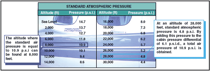
Figure 10: Standard atmospheric pressure chart.
Pressurization of the airplane cabin is an accepted method of protecting occupants against the effects of hypoxia. Within a pressurized cabin, occupants can be transported comfortably and safely for long periods of time, particularly if the cabin altitude is maintained at 8,000 feet or below, where the use of oxygen equipment is not required. The flight crew in this type of airplane must be aware of the danger of accidental loss of cabin pressure and must be prepared to deal with such an emergency whenever it occurs.
In the typical pressurization system, the cabin, flight compartment, and baggage compartments are incorporated into a sealed unit that is capable of containing air under a pressure higher than outside atmospheric pressure. On aircraft powered by turbine engines, bleed air from the engine compressor section is used to pressurize the cabin. Superchargers may be used on older model turbine powered airplanes to pump air into the sealed fuselage. Piston-powered airplanes may use air supplied from each engine turbocharger through a sonic venturi (flow limiter). Air is released from the fuselage by a device called an outflow valve. The outflow valve, by regulating the air exit, provides a constant inflow of air to the pressurized area.
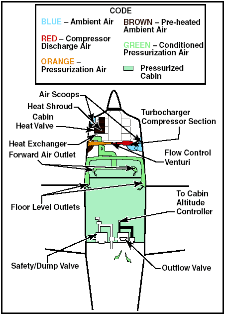
Figure 11: High performance airplane pressurization system.
To understand the operating principles of pressurization and air-conditioning systems, it is necessary to become familiar with some of the related terms and definitions, such as:
- Aircraft altitude—the actual height above sea level at which the airplane is flying.
- Ambient temperature—the temperature in the area immediately surrounding the airplane.
- Ambient pressure—the pressure in the area immediately surrounding the airplane.
- Cabin altitude—used to express cabin pressure in terms of equivalent altitude above sea level.
- Differential pressure—the difference in pressure between the pressure acting on one side of a wall and the pressure acting on the other side of the wall. In aircraft air-conditioning and pressurizing systems, it is the difference between cabin pressure and atmospheric pressure.
The cabin pressure control system provides cabin pressure regulation, pressure relief, vacuum relief, and the means for selecting the desired cabin altitude in the isobaric and differential range. In addition, dumping of the cabin pressure is a function of the pressure control system. A cabin pressure regulator, an outflow valve, and a safety valve are used to accomplish these functions.
The cabin pressure regulator controls cabin pressure to a selected value in the isobaric range and limits cabin pressure to a preset differential value in the differential range. When the airplane reaches the altitude at which the difference between the pressure inside and outside the cabin is equal to the highest differential pressure for which the fuselage structure is designed, a further increase in airplane altitude will result in a corresponding increase in cabin altitude. Differential control is used to prevent the maximum differential pressure, for which the fuselage was designed, from being exceeded. This differential pressure is determined by the structural strength of the cabin and often by the relationship of the cabin size to the probable areas of rupture, such as window areas and doors.
The cabin air pressure safety valve is a combination pressure relief, vacuum relief, and dump valve. The pressure relief valve prevents cabin pressure from exceeding a predetermined differential pressure above ambient pressure. The vacuum relief prevents ambient pressure from exceeding cabin pressure by allowing external air to enter the cabin when ambient pressure exceeds cabin pressure. The cockpit control switch actuates the dump valve. When this switch is positioned to ram, a solenoid valve opens, causing the valve to dump cabin air to atmosphere.
The degree of pressurization and the operating altitude of the aircraft are limited by several critical design factors. Primarily the fuselage is designed to withstand a particular maximum cabin differential pressure.
Several instruments are used in conjunction with the pressurization controller. The cabin differential pressure gauge indicates the difference between inside and outside pressure. This gauge should be monitored to assure that the cabin does not exceed the maximum allowable differential pressure. A cabin altimeter is also provided as a check on the performance of the system.
In some cases, these two instruments are combined into one. A third instrument indicates the cabin rate of climb or descent. A cabin rate-of-climb instrument and a cabin altimeter are illustrated in Figure 12.

Figure 12: Cabin pressurization instruments.
Decompression is defined as the inability of the airplane´s pressurization system to maintain its designed pressure differential. This can be caused by a malfunction in the pressurization system or structural damage to the airplane. Physiologically, decompressions fall into two categories; they are:
- Explosive Decompression—Explosive decompression is defined as a change in cabin pressure faster than the lungs can decompress; therefore, it is possible that lung damage may occur. Normally, the time required to release air from the lungs without restrictions, such as masks, is 0.2 seconds. Most authorities consider any decompression that occurs in less than 0.5 seconds as explosive and potentially dangerous.
- Rapid Decompression—Rapid decompression is defined as a change in cabin pressure where the lungs can decompress faster than the cabin; therefore, there is no likelihood of lung damage.
During an explosive decompression, there may be noise, and for a split second, one may feel dazed. The cabin air will fill with fog, dust, or flying debris. Fog occurs due to the rapid drop in temperature and the change of relative humidity. Normally, the ears clear automatically. Air will rush from the mouth and nose due to the escape of air from the lungs, and may be noticed by some individuals.
The primary danger of decompression is hypoxia.
Unless proper utilization of oxygen equipment is accomplished quickly, unconsciousness may occur in a very short time. The period of useful consciousness is considerably shortened when a person is subjected to a rapid decompression. This is due to the rapid reduction of pressure on the body—oxygen in the lungs is exhaled rapidly. This in effect reduces the partial pressure of oxygen in the blood and therefore reduces the pilot´s effective performance time by one-third to one-fourth its normal time. For this reason, the oxygen mask should be worn when flying at very high altitudes (35,000 feet or higher). It is recommended that the crewmembers select the 100 percent oxygen setting on the oxygen regulator at high altitude if the airplane is equipped with a demand or pressure demand oxygen system.
Another hazard is being tossed or blown out of the airplane if near an opening. For this reason, individuals near openings should wear safety harnesses or seatbelts at all times when the airplane is pressurized and they are seated.
Another potential hazard during high altitude decompressions is the possibility of evolved gas decompression sicknesses. Exposure to wind blasts and extremely cold temperatures are other hazards one might have to face.
Rapid descent from altitude is necessary if these problems are to be minimized. Automatic visual and aural warning systems are included in the equipment of all pressurized airplanes.
Oxygen systems
Most high altitude airplanes come equipped with some type of fixed oxygen installation. If the airplane does not have a fixed installation, portable oxygen equipment must be readily accessible during flight. The portable equipment usually consists of a container, regulator, mask outlet, and pressure gauge. Aircraft oxygen is usually stored in high pressure system containers of 1,800 — 2,200 pounds per square inch (p.s.i.). When the ambient temperature surrounding an oxygen cylinder decreases, pressure within that cylinder will decrease because pressure varies directly with temperature if the volume of a gas remains constant. If a drop in indicated pressure on a supplemental oxygen cylinder is noted, there is no reason to suspect depletion of the oxygen supply, which has simply been compacted due to storage of the containers in an unheated area of the aircraft. High pressure oxygen containers should be marked with the p.s.i. tolerance (i.e., 1,800 p.s.i.) before filling the container to that pressure. The containers should be supplied with aviation oxygen only, which is 100 percent pure oxygen. Industrial oxygen is not intended for breathing and may contain impurities, and medical oxygen contains water vapor that can freeze in the regulator when exposed to cold temperatures. To assure safety, oxygen system periodic inspection and servicing should be done.
An oxygen system consists of a mask and a regulator that supplies a flow of oxygen dependent upon cabin altitude. Regulators approved for use up to 40,000 feet are designed to provide zero percent cylinder oxygen and 100 percent cabin air at cabin altitudes of 8,000 feet or less, with the ratio changing to 100 percent oxygen and zero percent cabin air at approximately 34,000 feet cabin altitude. Regulators approved up to 45,000 feet are designed to provide 40 percent cylinder oxygen and 60 percent cabin air at lower altitudes, with the ratio changing to 100 percent at the higher altitude.
Pilots should avoid flying above 10,000 feet without oxygen during the day and above 8,000 feet at night.
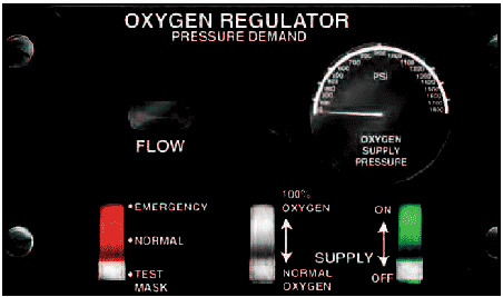
Figure 13: Oxygen system regulator.
Pilots should be aware of the danger of fire when using oxygen. Materials that are nearly fireproof in ordinary air may be susceptible to burning in oxygen. Oils and greases may catch fire if exposed to oxygen, and cannot be used for sealing the valves and fittings of oxygen equipment. Smoking during any kind of oxygen equipment use is prohibited. Before each flight, the pilot should thoroughly inspect and test all oxygen equipment. The inspection should include a thorough examination of the aircraft oxygen equipment, including available supply, an operational check of the system, and assurance that the supplemental oxygen is readily accessible. The inspection should be accomplished with clean hands and should include a visual inspection of the mask and tubing for tears, cracks, or deterioration; the regulator for valve and lever condition and positions; oxygen quantity; and the location and functioning of oxygen pressure gauges, flow indicators and connections. The mask should be donned and the system should be tested. After any oxygen use, verify that all components and valves are shut off.
Masks
There are numerous types of oxygen masks in use that vary in design detail. It would be impractical to discuss all of the types on this page. It is important that the masks used be compatible with the particular oxygen system involved. Crew masks are fitted to the user´s face with a minimum of leakage. Crew masks usually contain a microphone. Most masks are the oronasal type, which covers only the mouth and nose.
Passenger masks may be simple, cup-shaped rubber moldings sufficiently flexible to obviate individual fitting. They may have a simple elastic head strap or the passenger may hold them to the face.
All oxygen masks should be kept clean. This reduces the danger of infection and prolongs the life of the mask. To clean the mask, wash it with a mild soap and water solution and rinse it with clear water. If a microphone is installed, use a clean swab, instead of running water, to wipe off the soapy solution. The mask should also be disinfected. A gauze pad that has been soaked in a water solution of Merthiolate can be used to swab out the mask. This solution should contain one-fifth teaspoon of Merthiolate per quart of water.
Wipe the mask with a clean cloth and air dry.
Diluter demand oxygen systems
Diluter demand oxygen systems supply oxygen only when the user inhales through the mask. An automix lever allows the regulators to automatically mix cabin air and oxygen or supply 100 percent oxygen, depending on the altitude. The demand mask provides a tight seal over the face to prevent dilution with outside air and can be used safely up to 40,000 feet. A pilot who has a beard or mustache should be sure it is trimmed in a manner that will not interfere with the sealing of the oxygen mask. The fit of the mask around the beard or mustache should be checked on the ground for proper sealing.
Pressure demand oxygen systems
Pressure demand oxygen systems are similar to diluter demand oxygen equipment, except that oxygen is supplied to the mask under pressure at cabin altitudes above 34,000 feet. Pressure demand regulators also create airtight and oxygen-tight seals, but they also provide a positive pressure application of oxygen to the mask face piece that allows the user´s lungs to be pressurized with oxygen. This feature makes pressure demand regulators safe at altitudes above 40,000 feet.
Some systems may have a pressure demand mask with the regulator attached directly to the mask, rather than mounted on the instrument panel or other area within the flight deck. The mask-mounted regulator eliminates the problem of a long hose that must be purged of air before 100 percent oxygen begins flowing into the mask.
Continous flow oxygen system
Continuous flow oxygen systems are usually provided for passengers. The passenger mask typically has a reservoir bag, which collects oxygen from the continuous flow oxygen system during the time when the mask user is exhaling. The oxygen collected in the reservoir bag allows a higher aspiratory flow rate during the inhalation cycle, which reduces the amount of air dilution. Ambient air is added to the supplied oxygen during inhalation after the reservoir bag oxygen supply is depleted. The exhaled air is released to the cabin.
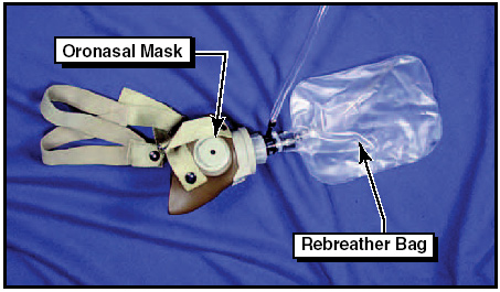
Figure 14: Continuous flow mask and rebreather bag.
Servicing of oxygen systems
Certain precautions should be observed whenever aircraft oxygen systems are to be serviced. Before servicing any aircraft with oxygen, consult the specific aircraft service manual to determine the type of equipment required and procedures to be used. Oxygen system servicing should be accomplished only when the aircraft is located outside of the hangars. Personal cleanliness and good housekeeping are imperative when working with oxygen. Oxygen under pressure and petroleum products create spontaneous results when they are brought in contact with each other.
Service people should be certain to wash dirt, oil, and grease (including lip salves and hair oil) from their hands before working around oxygen equipment. It is also essential that clothing and tools are free of oil, grease, and dirt. Aircraft with permanently installed oxygen tanks usually require two persons to accomplish servicing of the system. One should be stationed at the service equipment control valves, and the other stationed where he or she can observe the aircraft system pressure gauges. Oxygen system servicing is not recommended during aircraft fueling operations or while other work is performed that could provide a source of ignition. Oxygen system servicing while passengers are on board the aircraft is not recommended.